Science fiction is missing a realistic and grounded
look at particle beams. We plan to do just that now.

After reading this, you might decide to give
particle beams their rightful place alongside lasers as a means of transmitting
power, propelling spacecraft or dealing damage at long distances.
We then move on plausibly extrapolated performance and then to informed speculation on how they can be designed and used before ending on topics most relevant to sci-fi authors and worldbuilders.
Particle Beams
A particle beam is a stream of electrons, ions or neutral atoms that have been accelerated to a high velocity by an accelerator from a particle source.
Particle beams are used in a huge variety of ways. Everything from electron microscopes to cancer treatment involves a particle beam. A common example of a particle accelerator is a medical X-ray. It produces a beam of electrons that emit X-ray light when they hit a metal target.

They are used in research extensively. Some of the most expensive research projects ever are centred around particle accelerators, such as the Large Hadron Collider or the Stanford Linear Accelerator Center. The beams produced there are usually composed of electrons or protons, but also heavy ions such as lead and uranium. In fact, any charged particle can be accelerated in a particle accelerator.


This technology was also a focus of the Strategic Defense Initiative back in the 1980s, which culminated in an accelerator-equipped satellite being launched into space to test the performance of particle beams at different altitudes.
To describe the characteristics of particle beams, we could use standard units such as velocity in meters per second or particle energy in joules. However, the typical beam is highly relativistic (90%+ the speed of light or 0.9 C) and each particle has a very small amount of energy (a hundredth billionth of a joule or less).

A specialized set of units is used instead and a relativistic energy calculator is the best tool to handle them.
We use the Beta factor B, with values between 0 and 1, to describe the ratio of particle velocity to the speed of light. B = 0.875 means that the beam is travelling at 0.875 C.
The Lorentz or Gamma factor describes the intensity of the relativistic effects. A 0.875 C, a particle has a gamma factor of 2.065, meaning that it experiences time 2.065 times slower than anyone else around.
The relativistic energy calculator provides these values. If we input an ion mass (carbon has 12 g/mol molar mass so put ‘12’ in the mp box) and an ion energy (3.2 * 10^-8 joules, equivalent to about 2 * 10^9 electronvolts or 2 GeV), we obtain a Beta of 0.528 and a Gamma of 1.177. If we have a current of these carbon ions travelling in a beam (for example, 0.00001 Amps or 10 uA), we can multiply it by the particle energy in eV to work out the total beam power in watts (2 GeV * 10 uA : 20,000 watts or 20 kW).
These figures will be critical to understanding the performance and requirements of a particle accelerator.
The accelerator

The characteristics of a particle accelerator are resumed in their efficiency (%), acceleration gradient (volts per meter or V/m) and mass per meter length (kg/m). Launching and building equipment in space is inherently expensive. Moving it around is even more so. The expense is proportional to the equipment mass, so the best accelerator is therefore the one which has the highest performance per kg. High efficiency is good, because it means less mass dedicated to cooling systems. A high acceleration gradient is desirable for shorter and lighter accelerator. A low mass per meter is also needed.
It is with these characteristics that we evaluate the major types of particle accelerator.
The first and oldest type is the electrostatic accelerator. It works by applying a strong voltage difference between an anode and a cathode, separated by a gap. The maximum voltage possible is limited by electrostatic breakdown, which is when electrons jump across the gap on their own.

Van de Graff accelerators are the primary example of this design. Currently, the maximum voltage is roughly 25 million volts (MV), with the acceleration gradient averaging 0.5 MV/m.

Tandem electrostatic generators have achieved 40 MV in total.
To achieve higher energies and better acceleration gradients, induction accelerators are used.
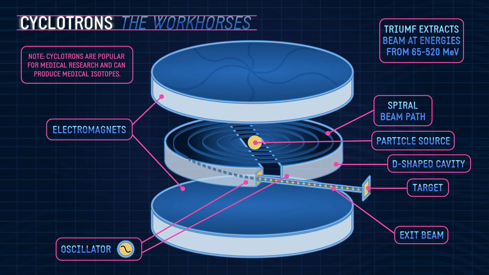
Betatrons are an example of this design, and they are a type of cyclotron. The acceleration gradient is about 1MV/m, but it quickly falls when the particles start reaching relativistic velocities.
Radio-frequency accelerators are the dominant type of high-energy accelerator in use today.

They use radiofrequency (RF) cavities to produce a voltage difference that particles are accelerated over. The cavities are simply 'mirror boxes' for radio waves. They bounce up and down at a very specific rate within the boxes. When a particle beam enters one end of the cavity, it encounters the radio wave. The wave has an electric field that pulls the beam along, which corresponds to a voltage.

Once the particle beam exits the cavity, it enters a drift tube that shields it from the radio wave's pull in the opposite direction. A series of cavities continuously accelerates the beam in this way. Dividing the voltage difference between the ends of the cavities by the distance the beam crosses gives us an acceleration gradient. Typical particle accelerators have an acceleration gradient of 20 MV/m. They are limited by RF waves being absorbed in the walls as heat.
The alternative is to use superconducting RF accelerators.

Cryogenically cooled cavities made of niobium metal have no electric resistance and do not absorb the RF waves. This means that very high acceleration gradients are possible without worrying about heating problems.

Superconducting RF (SRF) accelerators regularly reach 25 to 40 MV/m.

Certain configurations, such as travelling wave accelerators, are needed for highly relativistic electrons, but it is not the case for much more massive ions. This allows very short accelerators reach very high energies.
SRF accelerators can be circular or linear.
Circular accelerators allow a short acceleration length to be used again and again.

However, it needs powerful and therefore heavy magnets to keep bending a beam into a circle as the particle energies increase. Furthermore, bending a beam releases synchrotron radiation that drains particle energy. A small circular accelerator that can fit inside a spaceship would be limited in the particle energies it can achieve and would have multiple sources of inefficiency.
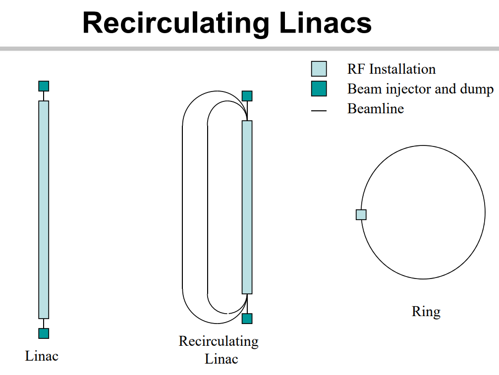
Linear accelerators or ‘linacs’ do not bend the beam. All energy expended goes towards accelerating the beam. Only a single pass is possible however, so strong acceleration gradients are needed.
You don’t have to choose strictly one or the other. A circular accelerator can be used to bring particles up to speed and then pass them onto a linac for the final boost. A recirculating linac could be selected as a sort of hybrid: after passing through the accelerating section, the beam is turned 180 degrees for a second pass.
Whatever the choice of the exact configuration, the SRF accelerator on a spaceship will have a length and therefore mass proportional to the particle energy we want to achieve. If we want particles with an energy of 100 MeV, we divide the energy by the number of charges and the acceleration gradient to find the accelerator’s length. For example, Oxygen 2+ ions and a 25 MV/m gradient would reach 100 MeV in just 2 meters while Lithium 1+ ions and a 10 MV/m gradient would need 10 meters.
A new accelerator technology has emerged in recent years: plasma wakefield accelerators.


They use an intense laser pulse to create a tube of plasma emptied of electrons. The electrons rush back in as a wave. Multiple pulses create a series of waves travelling at relativistic velocity. They can pull along particles in their ‘wake’, allowing for extreme acceleration gradients on the order of 10 GV/m. However, their efficiency is abysmal (~0.1%) and their acceleration lengths are in the centimetres, making them unsuited for anything but researchers. Even more recent developments could remedy their faults.
For the rest of this post, we will assume that SRF linacs are being used.
Particle beam divergence
In space, distances are huge. Particle beams would have to traverse thousands of kilometers to be useful. Divergence is very important in space because of these distances.

Divergence is the ratio of lateral spread to forward motion, noted in radians. For most cases described here, we will use milliradians ‘mrad’ or microradians ‘urad’. To correct for relativistic factors, it must be further divided by the gamma factor ‘y’.
A high divergence means that the beam spreads its energy over a large area within a short distance, making it hard to use for purposes such as power transmission or propulsion. A low divergence allows it to be focused onto a spot small enough to become a damaging weapon. The lower the divergence, the greater the range at which a beam remains useful.
Particle beams are said to spread too quickly to be used over long distances. This is true… for charged particle beams.

All accelerators produce charged particle beams. The self-repulsion between ions of similar charge causes electrostatic bloom. This is a very rapid widening of the beam that de-focuses it and spreads its energy rapidly. Even worse, if a beam were near a planet’s magnetic field, its trajectory would be bent off-course. Shooting charged particle beams also confers a strong electrostatic charge to the firing platform, which could lead to dangerous sparks and arcs.
The radius doubling distance for a charged particle beam is:
- RDD = 5586 * BR * B^1.5 * y^1.5 * (M / (Z * IB))^0.5
RDD is the radius doubling distance in meters.
BR is the initial beam radius in meters.
B is the Beta factor.
y is the Gamma factor.
M is the ion mass in g/mol.
IB is the beam current in Amps.
Z is the particle charge.
We can work out that a 0.1 mA beam of 200 MeV carbon ions with a charge of 3+ (B: 0.186, y: 1.02, IM: 12 and Z: 3) and an initial radius of 0.1 m would have a radius doubling distance of 9,232 meters. It crosses this distance in 165 microseconds. Because the radius increase causes the doubling distance to also increase, it would take 330 microseconds for the radius to double from 0.2 to 0.4 m, and 660 microseconds to increase from 0.4 to 0.8 meters and so on.

Charged particle beams cannot cross the thousands to tens of thousands of kilometers that separate objects and ships in space without expanding to huge sizes.
It doesn’t have to be this way though.
Electrostatic bloom can be prevented by taking an extra step after a charged particle beam passes through an accelerator: neutralization. This converts charged particles into neutral atoms, either by adding or subtracting electrons. Neutral beams do not suffer from electrostatic bloom but are still affected by thermal expansion.

Thermal expansion is due to the random motion of particles within the beam. This motion is the same as that of molecules within a gas and is proportional to the temperature and molar mass of the particles.
Perfect gas laws allow us to work out the velocity of the particles that results in thermal expansion. The velocity of particles in a gas depends on their temperature and molar mass. Specifically, the velocity in meters per second is equal to 17009.6 * (Temperature/Molar mass)^0.5, if we use electronvolts for temperature and g/mol for molar mass.
Lithium particles with a temperature of 1 eV and a molar mass of 7g/mol would expand by 6.43 km/s in all directions. This is negligible velocity in the longitudinal direction (the lithium particles would be accelerated to several thousands of km/s by the accelerator) but is critical in the transverse directions.
Divergence is the simple ratio between the beam’s rate of expansion and rate of travel. If we divide the transverse velocity by the beam velocity, we get a divergence in radians. Multiplying that divergence by the distance the beam must travel gives the beam radius at the distance. It is also called the spot radius, analogous to the size of a spotlight’s spot on the ground.
If a lithium beam were accelerated to a velocity of 72,330 km/s (a beam energy of 200 MeV), and it had a temperature of 1 eV, we can work out a divergence of 0.0000889 radians, or 88.9 microradians. If the beam must travel 1,000 km, it would have a beam radius of 88.9 meters (and a beam diameter of 177.8 meters). Its energy would be spread over the surface area of that spot.
By reducing the temperature or increasing the particle mass, we could expect a lower divergence. If we used ions with a temperature of 0.1 eV instead of 1 eV, we would expect a 3.16 times lower divergence. If we switched out the lithium ions (7 g/mol) for Cesium ions (133 g/mol), we would expect a 4.36 times lower divergence. A lower divergence allows for a smaller spot size at all distances and a better focusing of the beam’s energy.
This is where most writing on particle beams ends. Further research has shown that particle beam divergence is not so simple.
A heavier particle, for example, would also be travelling proportionally slower. Divergence is a ratio, and if both the transverse and longitudinal velocity are reduced by the same amount, the ratio is maintained.
Beam temperature is a complex topic. Superconducting accelerators with good control over the beam should cause next to no heating of the particles. What determines the temperature in the first place then?
What of all the other factors that go into determining the rate of beam spread? Why does ‘divergence’ not give many search results online?
This is because actual particle physicists use a different measure for the performance of accelerators: emittance. Let’s try to explain what it is and use it to answer our questions.
Emittance, emittance growth and ion sources
In scientific literature, the divergence of a particle beam is rarely given or used. ‘Emittance’ is used in its place. It is the result of multiplying the divergence of a beam by its radius to produce a measure in ‘meters-radians’. Because of the low values in most accelerators, ‘millimeters-milliradians’ or mm-mrad is preferred. One m-rad is a million mm-mrad.
In scientific literature, the divergence of a particle beam is rarely given or used. ‘Emittance’ is used in its place. It is the result of multiplying the divergence of a beam by its radius to produce a measure in ‘meters-radians’. Because of the low values in most accelerators, ‘millimeters-milliradians’ or mm-mrad is preferred. One m-rad is a million mm-mrad.
Emittance describes the average spread of particles, like divergence does, but it also helps factors in the width of the beam, any perturbations or errors, any imperfections in the accelerator and other factors.
A ‘normalized’ emittance divides the measured emittance by the gamma factor to account for any relativistic effects.
Emittance is more useful that simple divergence because it is flexible and can be applies to different accelerators that can be scaled, stretched or used in different ways… so long as the parameters determining the emittance are similar.
To get divergence back from emittance, use this:
- Divergence: Emittance / (Beam radius * 10^6)
Divergence will be in radians.
Emittance is in mm-mrad.
Beam radius is in meters.
Emittance is a very useful measure for predicting the performance of future accelerators. If we took the results of a small laboratory accelerator with a 1 mm wide beam, we can work out the divergence of a beam from a scaled-up version with a 10 cm wide beam.
Sadly, emittance is reported very inconsistently. One emittance reading in one paper will mean something different from another reading in another publication. The way emittance is reported has changed over time too. Early studies could give a figure in ‘mm-mrad’ that did not take into account relativistic effects. More recent paper would give ‘normalized’ emittance in ‘π mm-mrad’. To convert from one to another, you’d have to divide by π and calculate the gamma factor… despite both being called ‘emittance’. Also pay attention to whether the value is reported at the entrance, midway or at the exit of the accelerator. To muddle things further, emittance can count the beam radius as starting from different distances from the beam centre, creating hugely varied readings for the same beam.

With all these caveats in mind, we can start to take a quick look at the emittance of past and present accelerators.
-0.43 mm-mrad for the Indian Spallation Neutron Source,
-0.2 mm-mrad for TRASCO 100 MeV proton design.
-0.2 mm-mrad for the Independent Superconducting Cavity Linac,
-0.25 mm-mrad for the variety of heavy ions from the ATLAS accelerator,
-0.16 mm-mrad from the hydrogen ion accelerator specifically designed to lower divergence in the BEAR experiment,
-0.06 mm-mrad for the FRANZ proton linac,
As we can see, there is potential to improve. If you look into the documents linked above, you will see multiple emittances reported, at the exit of injectors or at the entrance of accelerators and so on. As the beam travels through the accelerator, it is disturbed a small amount by magnetic fields and heated up slightly by inter-particle collisions. This leads to a gradual increase in emittance from entry to exit. We call this ‘emittance growth’.
Much effort has been put into reducing emittance growth.
As we can see from these studies, emittance growth in modern accelerators can be as low as 5% or as high as 90%.
The valuable truth is stated in the introduction of this paper: emittance is due mainly to the ion source.
Ion sources are therefore the primary determinants of an accelerator’s emittance. We can see in the BEAR experiment that the emittance at the exit of the ion injector is the same as that at the exit of the entire accelerator.

An ion source, as the name states, is the device that feeds an accelerator with ions. There are a large number of options with different currents (charged particles per second released), current densities (current per area), efficiencies, voltages and other parameters.
We won’t detail the entire list. In general, ion sources are a small fraction of the power consumption, weight and size of a particle accelerator. However, the properties of the beam produced by an ion source determine the overall performance. It makes sense that we would select ion sources that produce high quality beams even if we must sacrifice efficiency or equipment mass to produce them.
As we will prove again later, having an ion source with a low emittance is crucial to a low final divergence of the particle beam. Searching through published performance of ion sources finds emittances as low as 0.004 (hydrogen) to 0.0075 (argon) mm-mrad.

- Ion Source Emittance = 65 * Aperture Radius * (T/M)^0.5
Emittance will be in mm-mrad.
Aperture radius must be in meters.
T is in eV.
M is molar mass in g/mol.
Inputting the figures from the study (0.1 eV Argon 1+ beam of 18 g/mol, leaving through a 1.5 mm radius aperture) we find a very similar emittance of 0.0073 mm-mrad.
To bring this back to divergence for a moment, we can work out that the MBE-4 linacs have a divergence of 4.8 microradians.
The equation also suggests that the smaller the aperture of the ion source, the smaller the emittance. However, the ion current is proportional to the surface area of the aperture, so this might limit how much current is available… unless multiple small radius ion sources are combined into one beam to have the best of both worlds: lowest emittance and high current.

Another way around a low current is to use a pulsed mode of operation. A small, lightweight low-energy storage ring can accumulate the output of an ion source working continuously and release it periodically in a high current burst.
The low emittance from an ion source like the one used in the MBE-4 linac is only possible because it produces ions with single charges. They require the least heating and the least intense magnetic fields to handle.
In many cases, an ion with multiple charges is desirable. An ion with more charges gains energy proportionally faster than an ion with less charges. An Uranium 12+ ion, for example, would gain 120 MeV of energy after passing through a 10 MV accelerating gradient. An Uranium 35+ ion would gain 350 MeV instead. The potential reduction in the accelerator length required to reach a certain energy level is very interesting as it would lead to great reductions in accelerator mass.
The best source for highly charged ions is the Electron Cyclotron Resonance ion source.

It is capable of handling all elements and achieving very high charge states by bombarding ions with an energetic electron beam again and again. The collisions deliver the required ionization energy to the ions, which can reach several keV.

The ions are forced to orbit within a small circle by magnetic fields so that they can be contained. However, the rotation within the magnetic fields adds a radial velocity to the ions. The result is an emittance dominated by the strength of the magnetic fields and the charge to mass ratio of the ions.

The equation for the emittance of an ideal ECR ion source is:
- ECRIS emittance: 0.032 * Aperture Radius^2 * B / MCR
Emittance is in mm-mrad.
Aperture Radius is in millimeters.
B is the magnetic field strength in Tesla.
MCR is the mass to charge ratio.
For heavy ions, B is about 0.5 to 2 Tesla and the MCR for something like Oxygen 2+ is 16 over 2 (which is 8). We find emittances as low as 0.03 to 0.05 mm-mrad using heavier elements Bismuth and Krypton. With an ECRIS, we want the heaviest ions and the smallest apertures to minimize emittance.

ECRs can become rather heavy. They need large magnets and consequent cooling systems. For cases where achieving the lowest possible emittance is not a priority but producing highly charged ions is, there exists an alternative: foil or gas strippers.
It involves two steps. First, an ion is given a small charge and accelerated to moderately high energies by a separate accelerator. The ion then impacts the stripper, which is a certain length of gas (light ions) or a certain thickness of metal (heavy ions). The impact releases enough energy to strip off a large portion of the electrons around the ion. Extreme charge states are possible, such as Pb 82+, if the particles were given sufficient energy to start with.

The stripping process leaves most of the beam’s energy preserved, but emittance suffers. Modern ion strippers achieve emittances on the order of 0.1 mm-mrad.
Emittance alone is not enough to make a particle beam useful. A very low emittance in a beam released through a very small opening still makes for a high divergence beam. In ion sources, trying to achieve a lower emittance also involves making their aperture even smaller, which does not lead to improvements in divergence.
If particle beams cannot achieve low enough divergence, then lasers will remain as the better option...
Beam optics

The beam radius can be increased through the use of beam optics. Increasing the radius of a beam with low emittance will lead to a very low divergence. Just like beams of light that can be bent, focused or defocused by lenses, particle beams can be manipulated using electrostatic or magnetic lenses.

Electrostatic lenses work by introducing a voltage gradient from a particle beam’s centre to its edge. A charged particle travelling near the centre is unaffected. A particle travelling nearer the edges is either pushed inwards (focusing) or pulled outwards (expanding) by the voltage gradient.

Electrostatic lenses become less effective as the beam velocity increases. This means that they work fine for non-relativistic beams but the voltage gradients needed to act on high energy beams quickly become impractical (electrostatic lenses are limited by the same 10MV/m as electrostatic accelerators).
Electromagnetic lenses use magnetic fields to deflect ions.

They become more effective as the beam velocity increases, allowing them to handle relativistic beams much more easily. They are larger and heavier than electrostatic lenses for the same focusing ability due to the need for strong magnets however.
Two lenses working together can decrease divergence. The beam would first be expanded from its narrow diameter to a larger diameter. Then its expansion would be corrected and it would be focused on a far-away spot. Emittance does not change during this process.
A 1 mm radius beam with 0.1 mm-mrad emittance would have a divergence of 0.1 mrad without beam optics. If it is expanded to 20cm, it would have a new divergence of 0.0005 mrad.

Beam expansion to reduce divergence can be found most prominently in the neutral particle beam space experiment ‘BEAR’ from the Los Alamos National Laboratory. It was and still is the only high powered particle beam flown into space. The accelerator produced a negatively charged hydrogen beam with a beam radius of 2mm, which was then expanded to 11mm by electrostatic optics. This would theoretically allow the divergence to fall by a factor 5.5 before neutralization.
The effect of magnetic lens radius on the size of beam spot at a certain distance is determined by:
- Spot radius = Emittance * Distance * 10^-6 / Lens Radius
Spot radius will be calculated in meters.
Emittance is in mm-mrad.
Distance must be given in meters.
Lens radius is also in meters.
You might notice that this is the equation used by lasers to determine spot size, if the wavelength of the photons were replaced by the emittance of the particles. In other words, a particle beam of emittance 0.1 mm-mrad has the same performance, given any distance and lens radius, as a laser of wavelength 100 nanometers (soft X-rays).
The implication is that particle accelerators can produce and handle beams with performance equal to lasers with extremely short wavelengths.
Neutralization
This is the step that allows a tightly focused particle beam to reach its destination without spreading into uselessness. Necessarily, it is the last step in a particle’s journey from ion source to space. After an ion becomes a neutral particle, it can no longer interact with magnetic fields and so cannot be further cooled, accelerated, focused or aimed.
Neutralization disturbs the particles in a beam. It imposes a minimum divergence that depends on the charge state of the ion, its energy and mass, and most importantly on the neutralization method being used. All neutralization requires an input of energy to strip an electron off a neutral ion, or releases energy when adding electrons to a positive ion. This energy is equal to the ionization energy.
Three main neutralization methods exist: using charge exchange, using electron beams or using lasers.
Charge exchange neutralization requires that an ion from a particle beam travel through a gas, plasma or foil.

When the ion strikes a component of that gas, plasma or foil, it gains or loses electrons and becomes a neutral atom. The advantage is that this method requires no power input (the neutralization energy comes from the beam itself) and can be a very lightweight solution.

The major downside is that impacts between an ion and a neutralizing particle tends to scatter the beam significantly. Gas or plasma neutralizers have the extra disadvantage of requiring heavy flow through a pressurized chamber, which is directly contrary to the requirement for keeping the accelerator tube in a perfect vacuum.

Design documents on the DEMO neutral beam injectors state that plasma neutralization becomes exceedingly inefficiency as particle energy increases above the 100s of keV. Gas neutralization fails above 1 keV. This is not a good solution for high energy particle beams.
Electron beam neutralization combines the ion beam with an electron beam of the same velocity.

The two beams merge into a plasma with an overall neutral charge. Within microseconds, the ions pull on the electrons to become neutral atoms. This is known as ‘recombination’. Recombination energy is equal to ionization energy.

As the electrons are travelling at the same speed as the ions, there are no impacts that scatter the beam. The massive mass difference between an electron and an ion means that the electrons retain almost all the energy being released by recombination. The electrons emit that energy as photons of specific wavelengths. The downside to this method is that you need an additional accelerator for the electrons and can only neutralize positive ions, but it is a small price to pay for the low divergence beams that are produced.
The latest option being developed is neutralization by lasers, also called photo-neutralization.

High energy photons from a short wavelength laser are sent to interact with an ion. The photons are absorbed by the outermost electrons of the ion. If enough energy is delivered to an electron, it jumps out of position. Photo-neutralization can turn negative ions into neutral atoms by removing electrons in this manner. The advantage is that photons are the most delicate neutralization tool and disturb the beam’s ions the least. However, it only works on negative ions and the laser power needed to strip high velocity beams after they have been expanded by beam optics is incredibly high.
- Photo-neutralization power = 8.853 * 10^-5 * BV * BR / Laser wavelength
Photo-neutralization power will be in watts.
BV is the beam velocity in m/s.
BR is the beam radius in meters.
Laser wavelength is also in meters.
That equation applies only to negative H ions. We work out that at 1 GeV energy (262,000 km/s) and in a beam 1 m wide (BR 0.5), we would need a laser power of over 11.6 GW when using the longest practical wavelength of 1 micrometer. This is to neutralize just 63% of the beam. Neutralizing a full 98% of the beam requires 46.4 GW.

This paper describes the development of an optical cavity that can bounce the laser up to 10,000 times through the particle beam to reduce the power required down by a factor 10,000. In our case, it is a reduction down to 4.64 MW. In non-laboratory conditions, that cavity might not have the same performance, but the real problem is that your multi-megawatt particle accelerator also needs a multi-megawatt laser to neutralize it.
Considering the characteristics of all these methods, we will focus on electron beam neutralization. There will be designs for which the other methods make sense, such as a single-use close range particle beam using a foil stripper or an interplanetary ultra-low-divergence power transmission beam using a photo-neutralizer, but we won’t focus on those here.
Let's continue to look at electron beam neutralization.

When adding or removing charges from an ion, they get a ‘momentum kick’ that can be seen as the difference in beam velocity before and after neutralization. The minimum divergence imposed by neutralization is:
- Neutralization divergence = (0.56 * IE/M) / (B * C * y)
Neutralization divergence is given in radians.
IE is Ionization energy in eV.
M is Molar mass is in g/mol.
B is the particle beta.
C is the speed of light, about 3 * 10^8 m/s.
y is the Lorentz Factor.
For a hydrogen ion, ionization energy is 13.6 eV. At 100 MeV, beta is 0.428 and y is 1.1065. We can work out that the minimum divergence of such a beam is 53.6 nanoradians. If it is accelerated to 1 GeV energy, beta becomes 0.875, y is 2.065 and the minimum divergence becomes 14 nanoradians.
This divergence is to be added to that of the beam before neutralization. In the real world, the neutralization disturbance will be greater than the theoretical minimum.
You will notice that the ions with the lowest ionization energy per mass, accelerated to the highest energies, will have the lowest minimum divergence. Cesium, for example, is particularly good. It has an ionization energy of just 3.89 eV while having a mass of 133 g/mol. At 250 MeV of energy, Cesium would have a minimum divergence of 0.86 nanoradians. Francium is even better but it is rare and very radioactive.
Bright beams?

The neutralization step releases the excess energy from recombination in the form of photons. Recombination usually involves the release of a photons with a total energy equal to the ionization energy.
The SDI proposal for neutral particle beams used gas strippers for hydrogen atoms. It was expected for about 7% of the atoms to exit the stripper in a metastable excited state. Shining a laser on those metastable atoms would have caused them to quickly release their energy as 656 nm wavelength photons, which is a bright cherry red. Without the laser, it would take about 125 milliseconds for the photons to be released.
Different ions emit different photon wavelengths as a ‘Radiative Recombination Continuum’. Going straight from the excited state (the electron has just arrived) to the ground state (all excess energy has been released) is rare, with a graduated release much more likely.

For example, a lithium atom would release a photon with an energy of 5.39 eV and a Cesium atom would release photons with an energy of 3.89 eV. Any division of these energies would correspond to visible wavelengths.
Multiplying the ionization energy (1 eV = 1.6 * 10^-19 Joules) by the current (1 A = 6.242 * 10^18 atoms per second) gives the total watts of visible light being emitted. For 1 Amp of Cesium atoms, this is 3.89 Watts. For a 250 MeV beam, this means that 1.6 millionth of a percent of the beam energy becomes visible light. This ratio only gets worse for beams with higher particle energies. These watts are spread over the distance the beam travels during its recombination time.
In other words, particle beams could be visible, and will certainly be detected by sensors across even large distances, but they are mostly invisible to the naked eye.
As the beam traverses interplanetary space, it encounters about five million protons per cubic meter near Earth, falling to 300,000 per m^3 at Saturn’s orbit. A 10 nanoradian divergence beam would traverse a volume of about 0.015 m^3 over a distance of 10,000 km. It encounters 78.5 thousand particles at most. Even if even proton is is struck, and all of the collision energy between the protons and beam particles were absorbed, and all of that energy was to be re-radiated as visible wavelength photons, then this would only amount to 2.34 femtowatts per meter for 0.063 C particle, or 0.45 nanowatts per meter for 1 GeV particles.

Neither makes for visible beam.
The situation changes near a planet. The particle density above an atmosphere is much higher than in the interplanetary medium, even when hundreds of kilometers over the surface. At 1000 km altitude above Earth, there are enough particles to create a mass density of 5.85 * 10^-15 kg/m^3. This would release 0.8 W/m from a 1 m diameter 0.063 C beam and 201 W/m from a 0.875 C beam. Relativistic beams are likely to be visible to the naked eye when fired over an atmosphere.

Near the top of Earth's atmosphere, at 200 km altitude, we would expect very bright beams of 55.9 kW/m (0.063 C) or 10.78 MW/m (0.875 C). The huge energy losses experienced by fast beams make them impossible to use in such conditions unless they are very, very small (mm wide beams).
All in all, the particle beams are likely to be detected by sensors but unlikely to be visible to bystanders.
Final divergence
We now have all the elements in place to work out the divergence of a very good particle accelerator.
- Final divergence= ((SE/LR * EG * 10^-6 + 0.56 * IE/(M * BV))/y
SE is source emittance in mm-mrad (refer to the ion source equations).
LR is the lens radius in meters.
EG is the emittance growth throughout the accelerator, dimensionless.
IE is the ionization energy in eV.
M is the molar mass in g/mol.
BV is the beam velocity in m/s.
y is the gamma factor.
We can work out that a 10 meter long accelerator built using modern technology, using a Microwave Ion Source to produce extract single-charge Cesium ions with 0.0018 mm-mrad emittance, expanding the beam from 1 mm radius to 0.05 meter radius (LR = 0.05), causing 10% emittance growth (EG = 1.1) and using electron beam neutralization (IE 3.89, M 133, BV 18,900,000), could be expected to produce 250 MeV particles with a divergence of just 40.5 nanoradians.
This beam would cross a distance of 1,000 km in about fifty milliseconds and would remain focused within a spot just 8.1 cm wide.
Even better focused beams could be produced if negatively charged ions are accelerated.

The ionization energy for a negative ion can be very low, such as 0.47 eV for Cesium instead of 3.89 eV.
Bigger accelerators can use larger optics and achieve higher particle energies, making particle beam performance scale up favourably.
Equipment design

The mass of a particle accelerator system seems to be dominated by the RF power generators and the cooling system, at least according to a footnote on the SDI report on the feasibility of Neutral Particle Beam weapons for ballistic missile defence.
RF power, specifically in the frequencies that heavy ion SRF accelerators use, can be generated by solid-state devices. The best example of commercially available performance is from the Nautel generators produced specifically for the VASIMR rocket.

They operate at over 98% efficiency and have a power density of 2 kW/kg. However, they lose efficiency as the RF frequency asked of them increases.

For the dozens of MHz minimum that accelerators need, they are closer to 65% output efficiency.
Inductive Output tubes are another option.

This design by Relltubes produces an impressive 16 kW/kg at 73% output efficiency.
The low frequencies achieved by solid state devices or Inductive Output tubes limit them to accelerating the heaviest ions to rather low velocities. Higher frequencies are needed for light ions or to achieve relativistic velocities.
For higher RF frequencies required to push light particles to relativistic velocities, a magnetron is the best option.

The most modern designs boast 14.7 kW/kg at 88% output efficiency.
Solid state amplifiers, inductive output tubes or magnetrons can all expect to operate at rather warm temperatures. The amplifiers obtain good efficiency at room temperature (298 K) but can sacrifice efficiency down to operate at up to 473 K. The same goes for inductive output tubes, while magnetron performance seem to be unaffected by temperature even when operating at 423 K.
The Klystons needed for the highest frequencies struggle to surpass 1 kW/kg.

However, NASA designs for klystrons to be used in the SPS program were to achieve 1.96 kW/kg before cooling equipment was included.
These temperatures are critical for telling us whether the waste heat from the RF source can be radiated directly or requires heat pumps to increase the radiating temperature (at the cost of more electricity and equipment mass). Lighter radiators can accommodate lower temperature waste heat. Better heat pumps significantly reduces radiator mass.
For example a 1 MW magnetron would mass 68 kg and would need 95 kg of 1 mm thick graphite radiators radiating at 400 K to get rid of 120 kW of waste heat.
The RF power reflected in an accelerator’s cavities is not absorbed. Over 100 MW of RF power per meter length of accelerator is possible.
However, the superconducting walls are subjected to eddy currents from the megavolt electric field gradients running through them. These currents encounter a very small resistance, on the order of nanoOhms. Even cooling below 2 Kelvin temperatures cannot eliminate this ‘residual’ resistance.
Typical SRF efficiency is therefore about 99.9%. Residual resistance causes about 0.1% of the power that an accelerator handles to become heat in the cavity walls. A 1 MW accelerator, for example, would cause 1 kW of heating.
Most superconducting accelerators operate at 4.5 Kelvin temperatures to handle this heating.

The empty spaces around a cavity’s walls are actually filled with helium. Helium boils at 4.2 Kelvin in standard atmospheric pressure. Having the cavity walls sit at a temperature just above the boiling point of helium allows any heating to be carried away by helium’s phase transition from liquid to gas state.

The transition absorbs 20 kJ of heat per kg of helium. Accelerators that operate in the 4 to 5 Kelvin temperature range are made possible today through the use of niobium-tin alloys. A 1 MW accelerator should be prepared to lose 50 grams of helium per second.
For a spaceship that only intends to use the accelerator in short bursts, releasing the helium vapours into space is acceptable. If the usage period extends to many hours, it is advisable to use a cryogenic heat pump to compress the vapours and increase their temperature from 4.2 K to 13.8 K. The latter temperature is where liquid hydrogen boils in near vacuum. Using hydrogen as an expendable coolant instead of helium is much more interesting, as it can absorb 455 kJ/kg. Even with the increased heat load of the pumps, the coolant expenditure is reduced by a factor 10 with liquid hydrogen.

A closed loop alternative to expending helium or hydrogen is to install many more heat pumps to raise temperatures to the point where the heat can be effectively emitted from a radiator’s surface. A 300 Kelvin radiator emits 459.3 W/m^2 of exposed area. Pumping heat from 4.2 K to 300 K adds an additional 7042% to the heat load. If we want to get rid of 1 kW of heat, 7043 kW need to be emitted from 7667 m^2 of double-sided radiators.

The question is whether the mass dedicated to the heat pumps (14 tons at 500 W/kg as deduced from Lockheed’s aerospace cryocooler) and the radiators (17.6 tons for 1mm thick graphite fins) is advantageous compared to few grams per second of liquid hydrogen expenditure using the previous solution. Only serious improvements to heat pump technology can reduce the mass of equipment needed to carry heat across large temperature differences and make closed loop cooling a better alternative.
After the RF power source and the cooling equipment comes the mass of the accelerator cavities themselves.
We can work this out. A half-wavelength cavity made for particles of moderate relativistic velocity (0.6 to 0.9 C) has 59 kg of niobium per meter length according to this design. With its titanium structure, it comes out to 130 kg/m.

Other figures that we can use are those of the non-superconducting BEAR accelerator at 53.7 kg/m, the Indian IUAC at 316 kg/m or the much more modern cavities of the superconducting LHC at 125 kg/m. The main reason behind the mass per meter difference between the superconducting and non-superconducting cavities is the addition of a pressurized helium tank. We can settle on 130 kg/m as being a reasonable estimate. A 40 m long accelerator is expected to add 5.2 tons to equipment mass. This is expected to fall as technology progresses.
The beam must pass through an electromagnetic lens and a neutralizing step.

The High Energy Beam Transport section of the BEAR accelerator is an example of an electromagnetic lens. This is another example. All figures available online for magnetic lenses assume energetic beams being focused to a spot just a few centimeters to meters away from the lens. Deflecting the beam over such a short distance requires strong magnets, hence the improve magnet masses you can find. A particle accelerator in space will want to focus its beam over thousands to hundreds of thousands of meters. This greatly reduces the magnet strengths needed.

For example, a typical magnetic lens with an aperture of 10 millimeters will focus a beam over a distance of 1 meter. Our lens would have an aperture of 1 meter and focus a beam over a distance of 100,000 meters at a minimum. The magnetic field requirements for our lens would be about a thousand times lower than a typical magnetic lens.

For example, a 0.5m wide magnetic lens trying to focus 250 MeV heavy Cesium ions a spot 100 km away needs a magnetic field strength of just 0.000188 Tesla. In other words, the mass of magnetic optics for long range particle beams is negligible.
The neutralizing step requires an electron accelerator. Electrons of the same velocity as a heavy ion are very low energy particles. Producing and accelerating them therefore requires very little mass dedicated to electron accelerators, on the order of kilograms. For a 10 MW beam of 250 MeV particles, a Cesium current of 40 milliAmps is required. 40 milliAmps of electrons would be needed to neutralize the ions. The Cesium ions are travelling at 18,947 km/s so the electrons would need an energy of just 1 keV to reach the same velocity.

A 40 mA, 1 keV beam of electrons can be created by a <1 kg device.
Other equipment such as an ion source are a small contribution to overall mass.

A permanent magnet ECR called LAPECR1 managed 2.5 mA using just 25 kg of equipment.
An even better example is the Dresden ECRIS-2.45M ion source for low charge ions, where 10 mA can be produced by a device of just 35 kg. 40 mA of Cesium might need less than 0.14 tons.
Using the figures for modern accelerators, we can expect a 10 MW 250 MeV beam to require 0.14 tons for the ion source, 1.3 tons for the cavities, 0.68 tons for the RF power source, and 0.64 tons for 400 K radiators. We add a 25% ‘other equipment’ margin to bring the total mass to 3.45 tons. About 50.2 grams of liquid hydrogen coolant per second is the ‘ammunition’. The accelerator can fire for one hour with 180.7 kg of hydrogen on-board or for a full day (delivering 864 GJ) with 4.3 tons. Cesium consumption is negligible, at just 55 micrograms per second.
At this scale, the entire accelerator assembly would have a power density of 2.89 kW/kg. When more advanced technologies are included, such as better heat pumps or lighter radiators, the figure increases even further. For the rest of this post, we will use three designs:
Modern Accelerator
Output: 10 MW
Divergence: 40.5 nanoradians
Beam velocity: 18,900 km/s
Total mass: 3.45 tons.
The modern accelerator is built out of existing components as described above. The biggest contributors to the device’s mass are the cavities and the RF power source.
Huge Accelerator
Output: 500 MW
Divergence: 16.7 nanoradians
Beam velocity: 18,900 km/s
Total mass: 203 tons.
Some design changes made sense at a larger scale. Better radiators in the form of ‘wire radiators’ show benefits when 185 MW of waste heat must be removed from the RF generators. At smaller scales, the support structure needed to handle the 1 mm thick carbon fiber wires makes them uninteresting. The SRF cavities are heated significantly more by 500 MW of input power. Ejecting a huge load of hydrogen is wasteful at this scale, so a closed loop solution using 65.6 tons of heat pumps and 8.2 tons of nylon radiators operating at 300 K was selected. It ends up more mass efficient than open loop cooling after 8.8 hours of operation. A larger set of lens was also used, with 0.25 m width. Together, a power density of 2.46 kW/kg (even with +25% for other equipment) is achieved and the beam can be focused to a spot 33.4 cm wide at 10,000 km distance.
Advanced Accelerator
Output: 1000 MW
Divergence: 3.9 nanoradians
Beam velocity: 48,270 km/s
Total mass: 131.2 tons
In the advanced accelerator, we assume some technological progress has taken place. The RF power source is more efficient, at 85%, which increases its power density to 18.6 kW/kg. Heat pump technology moves to using superconducting electric motors to drive Brayton cycle compressors, increasing their power density to 5 kW/kg, which in turn allows them to be used to increase the temperature of all waste heat. The heat from RF generator and the SRF cavities is pumped up to 600 K, which allows for a very lightweight bubble membrane radiator to be used. Stronger materials can also allow for lighter SRF cavities, reducing them to 50 kg/m. We can therefore use a longer accelerator (50 m long at 33 MV/m) and a larger lens (1m wide). Adding on improvements to the ion source, we end up with an overall power density of 7.6 kW/kg and the ability to focus a 48,270 km/s beam to a spot just 39 cm wide at a distance of 50,000 km.

The particle beam cannot be bent after neutralization, and it becomes very hard to steer it using electromagnetic optics after it has reached high energies near the end of the accelerator. A reasonable configuration of all these components is to have a fixed ion source and low energy accelerator stages, and a moving high energy stage topped with a neutralizer. It would resemble a turret.
Power transmission and propulsion

The ability to focus a beam of high velocity particles onto a small spot over long distances has applications in transmitting power or spacecraft propulsion.
For power transmission, you need a beam accelerator and a receiver, separated by the distance you want to cross.
The beam accelerator is as described above. The receiver has three parts. The first part is the beam stripper, most likely a metal foil. A neutral beam cannot be converted into electricity without turning it back into a charged beam. After passing through the stripper, the beam becomes a plasma of electrons and ions. This plasma travels into the next part: the beam optics. Electromagnetic lenses (for relativistic beams) or electrostatic optics (for slow beams) attempt to brake and bend the beam. The effect on the lighter electrons is much greater than on the heavy ions, which leads to the electrons slowing down more and bending away from the main ion beam.
Once separated from its electrons, the ions are directed through the third part: the beam recuperator. It works like an accelerator in reverse and is a commonly proposed for use in fusion reactors to convert alpha products: instead of using electric fields to accelerate particles, it slows them down and converts its energy into electricity.

Direct energy conversion turns kinetic energy into electric energy with no intermediate steps. ‘Travelling Wave’ or ‘Inverse Cyclotron’ direct energy converters have a maximum efficiency of over 90% and can handle high particle energies. Similar power density is expected at either end of the power transmission, with RF generators replaced by power processing units at the receiving end.

A direct conversion receiver works best over distances where the beam does not spread too much.

A very wide beam would have to be handled by equally large beam optics, which become very heavy when scaled up. For example, the Huge Accelerator would produce a beam about 1 meter wide at a distance of 60,000 km. The Advanced Accelerator achieves this at a distance of 256,000 km. These are more than sufficient for carrying power between spacecraft, such as a booster mothership and a cargo tug, but not enough to transmit power over the distances between moons or planets. Increasing the transmission distance by a factor 10 would require beam optics over 100 times larger and heavier.
A different way of converting beam power into electricity can used to unlock the longer distances.
When a particle beam intersects a gas, collisions between the beam and gas molecules turn kinetic energy into heat.

A tube of gas can be used as a beam target, with the beam entering through a thin window of dense metal. The beam loses its energy by travelling through the gas, which is converted into heat with an efficiency approaching 100%. The hot gas is then used to power turbomachinery, much like a modern power reactor.

The best type design is one where the particle accelerates the heaviest particles possible to velocities just high enough so that they reach high charge states when striking the metal window. Heavy particles disperse the least and slow down the quickest when travelling through a gas, which keeps the transmission range high and the beaming tube short. A high charge state also helps them to slow down faster. An ideal ion is Uranium 238, which has a high mass, low ionization energy and low radioactivity.
The beaming tube should be filled with a high molar weight gas with a low heat capacity. The high molar weight allows for a higher density (kg/m^3) to slow down the beam in a shorter distance, while the low heat capacity allows for the gas to heat up to high temperatures to improve thermodynamic efficiency. Iodine is a good example, as it is sufficiently dense even at high temperatures (1.2 kg/m^3 at 10 atm pressure and 2500 K temperature in the form of the molecule I2) while being not as rare and expensive as Xenon nor likely to condense in the radiators (it boils at 457 K).

Efficiency of the beaming tube power transmission design suffers due to the intermediate thermodynamic step for converting beam energy into kinetic energy. If the beaming tube is 90% efficient, the Brayton turbomachinery 60% efficient and the alternator and power handling steps 90% efficient, the overall efficiency is 48.6%. Power generators seeking the highest possible power density will have a higher temperature Brayton cycle that minimizes radiator size but cuts into efficiency even further, down to 24.3% perhaps. This is roughly the efficiency of solar power.
The beaming tube power generator can operate at extreme distances away from the power source, does not rely on the sun and can achieve overall high power density.
A dedicated power source would use the extra equipment required to reduce the divergence of its heavy ion beam to the lowest possible value, roughly equal to that caused by the neutralization disturbance. For a 1000 MeV Uranium 238 beam, this can be as low as 0.45 nanoradians. A 20 m beaming tube would intercept 100% of this beam at a distance of 22 million km.
Another way to use a particle beam is to bounce it off a magnetic field in a propulsion system known as the ‘mag-sail’.

The slower the particle beam, the better the thrust per watts of the propulsion. The efficiency falls as the ratio of mag-sail velocity to beam velocity increases, but it can be ignored for interplanetary trips. For example, a 100 MW beam of 0.3 C particles would deliver 2.2 Newtons of thrust to a stationary mag-sail (45.5 MW/Newton), but a 0.01 C beam would deliver 66.6 Newtons (1.5 MW/Newton). The main advantage of mag-sails is that they can create huge reflecting field areas using lightweight conducting coils. Mag-sails prefer the use of lighter particles that are more easily reflected by magnetic fields after they are ionized, but this tends to negatively affect divergence.
Using Zubrin’s estimates, superconducting coils that can handle 1000 MA/m^2 of current can produce a magnetic field of 1 Tesla in a bubble nearly 500 m in diameter using loops massing just 10 tons. This mag sail is large enough to fully intercept a 1 nrad beam at distance of 250 million km or 1.7 AU. It could potentially catch 15.7% of a nanoradian beam across the 4.2 AU distance that separated Earth from Jupiter.
A 20 ton spaceship with a 10 ton magsail riding a 1 GW beam of heavy particles at a velocity of 0.01 C would accelerate at a rate of 22.2 mm/s^2. This is enough to cross the distance between Earth and Jupiter in about 17.6 weeks.

The field area can be further boosted by ejecting plasma, as is done by the M2P2 Mini-Magnetospheric Plasma Propulsion system.
We can also imagine a Particle Beam Thermal Rocket engine, where the beam is used to directly heat propellant.

This is similar to the Laser Thermal Rocket engine. Instead of optical mirrors, a stripping foil with bending magnets behind it can direct a particle beam into a reaction chamber filled with propellant. Particle beams can efficiently heat up propellant without the need for seeding particles, allowing for pure hydrogen gas to be used for maximal exhaust velocity. They can also ionize a good portion of the propellant gases, allowing for electromagnetically confined propellant that can reach very high temperatures without touching the chamber walls.
The main disadvantage is that a Particle Beam Thermal Rocket cannot work in an atmosphere.
Weaponry and damage mechanics

The ability of particle accelerators to focus their output onto a small area at a great distance has an obvious application as a weapon system.


First of all, how does a particle beam deal damage?
The ‘Report to the American Physical Society of the study group on science and technology of directed energy weapons’ is the golden reference for its section on Neutral Particle Beam weapons.
Two damage mechanisms prevail for the heavy ion particle beams discussed so far: radiation dose and volumetric heating.
High energy particles are considered as penetrating radiation. They do not deposit all of their energy on a target’s surface, but travel through a certain depth of matter before stopping. The depth depends on the properties of the beam and density of the target material. All energies discussed in this post are more than enough completely strip any electrons from an impacting particle. In fact, the target material acts like a 100% effective stripper. This is why the particles from a neutral hydrogen beam will be referred to as protons, and why previously neutral particles are described as ion in the following sections.
The main way that particles lose energy when traversing matter is due to collisions with the electrons surrounding atoms in the matter. The equation that governs how far a particle penetrates into matter is based on that effect:
- Penetration depth: 0.00331 * E^1.74 / (Z^2 * A^0.74 * D))
Penetration depth will be in centimetres.
E is the particle energy in MeV
Z is the particle charge state.
A is the particle molar mass in g/mol.
D is the target material’s density in g/cm^3
We can see that more energetic and lighter particles would penetrate the most, with protons being the best at traversing matter. In fact, any other particle than a proton is unlikely to penetrate significant lengths of any material due to 1/Z^2 factor.
A helium particle would gain 2 positive charges after impact while weighing 4 times more than a hydrogen particle. For the same energy, it penetrates 11.15 times less material than a hydrogen particle. This get much worse for heavier particles, with Cesium penetrating 112,817 times less than hydrogen.
We can safely ignore the penetrating effects of anything other than protons.
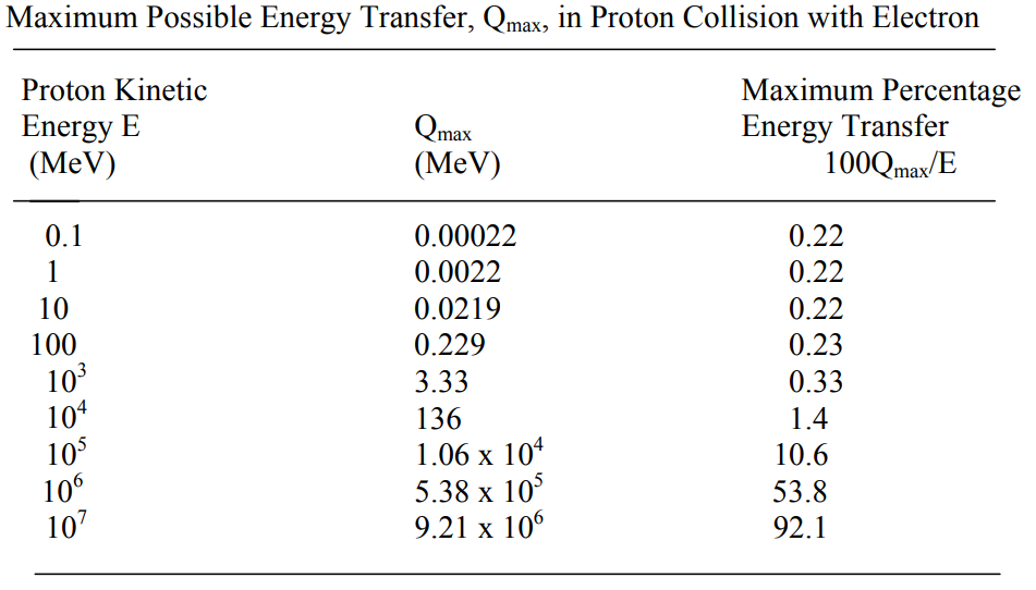
The penetration depth equation does not account for the changes in how protons interact with electrons at energy levels greater than 10 GeV.
The energy transfer from a proton to an electron increases rapidly beyond 1 GeV, which makes penetration rates fall below the expected values. At even higher energies, the protons cause multiple neutrons to be knocked out of the shielding material for every incident particle and can even create muons and pions… these are additional energy loss mechanisms that further affect penetration.

The shielding table from a CERN lecture empirically confirms that proton penetration rises more slowly for energies higher than 3 GeV. In other words, proton penetration at 3 GeV is the most efficient, but it can be increases further.
Another complication is that shielding full of hydrogen, such as water or plastic, is much more effective than the equation would suggest for the same g/cm^2 values.
From this table, we find a 29% discrepancy between the penetration depth calculated for 250 MeV protons (49 cm) and the value measured (38 cm).
It can all be summarized by the relative effectiveness of shielding materials:

We can see that water is again about 30% more effective than aluminium at great shielding amounts. Surprisingly, there are materials even more effective than water but are not liquid hydrogen, such polyethylene and lithium hydride requiring 45% less shielding than aluminium.
Considering all these complications, it is best to simply use the data collected in the physics databases made online by the National Institute for Standards and Technology. Using those databases, we will produce charts for the penetration of protons of 100 MeV to 10 GeV into polyethylene, water, carbon, steel, tungsten, lead and uranium.
Polyethylene:

Polyethylene has a density of 0.94 g/cm^3 so a 250 MeV proton would go through 38 cm and a 3 GeV one would go through 13 meters.
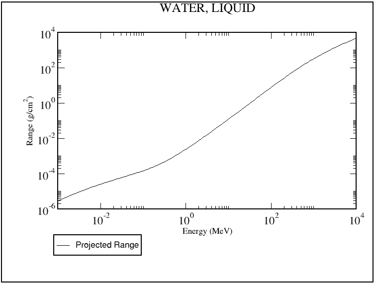
Water is 1 g/cm^3 so the y-axis can be read in centimeters. 250 MeV protons go through 35.7 cm and 3 GeV through 12.47 meters.
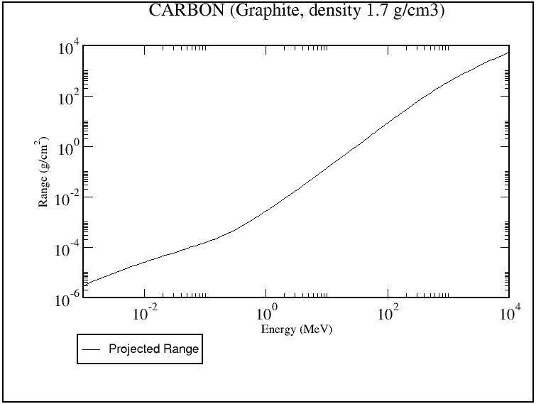
Graphite can have a density of 1.5 to 2.3 g/cm^3. Amorphous carbon has 2 g/cm^3 and diamond has 3.5 g/cm^3. For this graphite specifically, 250 MeV protons go through 24.9 cm and 3 GeV through 8.7 meters.
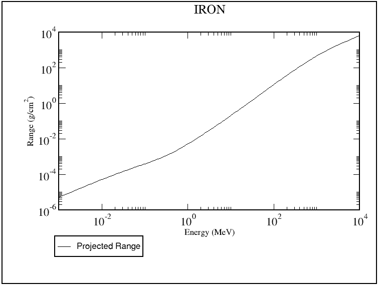
We use iron at 7.84 g/cm^3 to simulate steel. 250 MeV go through 6.92 cm and 3 GeV protons go through 2.31 meters.
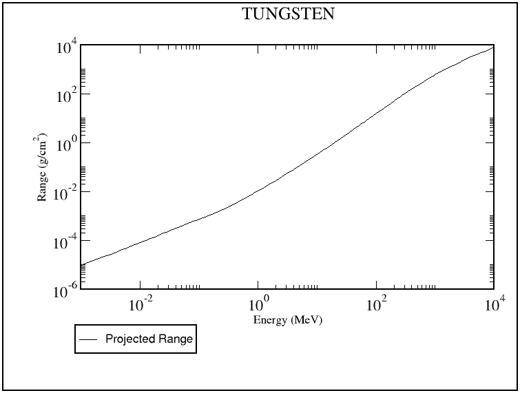
Tungsten at 19.3 g/cm^3 is interesting as it is dense, temperature resistant and strong. It stops 250 MeV protons within 3.7 cm and 3 GeV protons within 1.21 meters.
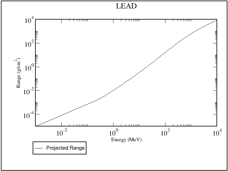
Lead is disappointing as it requires 6.6 cm for 250 MeV protons and 2.08 meters for 3 GeV protons.

Uranium is great as it stops 250 MeV protons within 4.6 cm and 3 GeV after 1.3 meters, but there is the danger of significant secondary radiation in the form of neutrons.
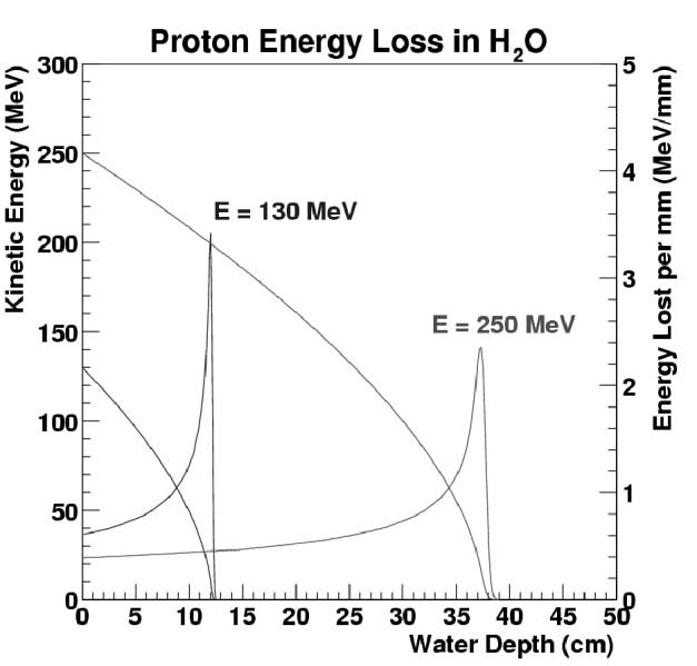
The energy of a proton is not deposited continuously throughout the penetration depth. As the particle slows down, the material becomes more effective at slowing it down further. At a certain point, usually for protons of less than 100 MeV, material stopping power increases very rapidly up to a maximum at 1 MeV. The Bragg peak is situated in this region
.
The heavier the particle, the narrower and sharper the Bragg peak is. More importantly, the Bragg curves indicate that shielding that is too thin to fully absorb a beam let through a lot more radiation than what you’d expect, up to 40% of a 250 MeV proton or 3% of a 3 GeV proton.
Whatever passes through the radiation shielding is fully absorbed by people or electronics. People and electronics do not like being hit by high energy particles.


The full effects and calculations of radiation doses are given on the Atomic Rockets website.
The only saving grace here is that when the highest energy protons encounter very thin or no shielding, they don’t slow down at all keep on going through the walls, people and electronics before exiting without losing much of their energy.

This is the reason behind NASA stating that aluminium walls on their spacecraft makes Galactic Cosmic Ray radiation worse by causing them to release more of their energy in people.
A completely unshielded human modelled as a 30 g/cm^2 target would absorb only 10% of a 1 GeV proton or 0.7% of a 10 GeV proton.
However, particle beams can be tailored to deal maximum damage. An over-penetrating beam can easily be detected leaving the target from the other side. The particle energy would then be adjusted so that the Bragg peak sits inside people or electronics. A large portion of the beam’s energy would then be released in the most damaging manner.

This is used to a good end in proton radiation therapy: 250 MeV protons deposit most of their energy in the center of a person. Weaponized protons would designed to have at most 250 MeV left over after passing through shielding to prevent over-penetration.
Insufficient shielding against weaponized radiation beams will be deadly in short order.
A 100 MW accelerator shooting 1 GeV protons with a divergence of 0.1 urad, facing shielding that lets through 100 MeV of energy per particle, would cause immediately lethal doses of 300 J/kg at a distance of over 59,467 km… in one second.
If the beam can be held on the target for just one minute, it can be lethal at a distance of 0.46 million km.
Electronics do not fare much better.

Sensitive devices used in sensors would be even less resistant than people. Electronics can survive a dose of 100 kJ/kg if they are extremely radiation hardened (at the cost of weight and performance). This decreases the lethal distance by a factor 18.25.

It should be noted that a 1000 MW beam would terminally irradiate targets in a period 10 times shorter, or at a distance 3.16 times further, than a 100 MW beam.
Protecting against such a beam would be of capital importance to having human crews anywhere near a space battle. Armor and defense schemes will be discussed in the next section.
If a proton beam does not fully penetrate the shielding, it will have almost all of its energy converted into heat instead. We can use the following equation to determine how much heat energy is deposited per m^3 of shielding material:
- Volumetric heating rate = BP / ((Divergence * D)^2 * 3.142*Penetration))
The heating rate is in W/m^3.
BP is Beam power in watts.
Divergence is in radians.
D is Distance in meters.
Penetration is in meters.
We can work out that the previous beam (100 MW, 1 GeV protons with a divergence of 0.1 urad), if encountering a thickness of shielding it cannot penetrate from 59,467 km away, would spread its energy over a volume 11.89 m wide and 2.15 m deep in graphite or 0.58 m deep in steel. The volumetric heating is 418.6kW/m^3 in graphite or 1552 kW/m^3 in steel. These figures can be converted into 182 and 197 W/kg respectively.
This heating can be ignored for temperature resistant materials such as graphite or steel, but could cause the best radiation shielding materials such as polyethylene or water to fail.
What is to be done if the particle beams cannot irradiate their target or cause sufficient volumetric heating?
You change the beam properties to maximize volumetric heating. Instead of a lightweight, penetrating particle, you choose a heavy atom with the lowest divergence possible. As we can see from the penetration equation, a higher mass and charge state reduces penetration. Heavy atoms striking solid matter quickly lose most or all of their electrons and achieve a multiply charged state.
A 250 MeV Cesium particle would only penetrate a distance of only 1.88 micrometers into graphite or 0.4 micrometers into steel. We will set 63 MJ/kg as the energy needed to vaporize carbon, which happens at a temperature of about 3600 K in vacuum. Steel sublimates at just 873 K in vacuum, requiring 6.3 MJ/kg. We can convert those figures into 144.9 GJ/m^3 for carbon and 54.2 GJ/m^3 for steel. If we divide the beam energy by the multiple of the beam area and the volumetric vaporization energy, we can get a penetration rate. This is the resulting equation:
- Penetration rate = Beam Power/(Spot Area * VVE)
Beam P is beam power in Watts
SA is the beam Spot Area in m^2, equal to ((Divergence * Distance)^2 * 3.142)
VVE is the volumetric vaporization energy in J/m^3.
That equation is only useful at shorter ranges, where the beam intensity is rather high. At the shortest ranges (a few hundred km), the beam causes explosive expansion of the target material and gains an even greater penetration rate from the pressure breaking up and excavating more material. At longer ranges, the beam spreads out enough for thermal conduction and blackbody radiation to sap away its power and reduce penetration significantly, or even stop it.
For a more accurate result, we would best use this laser damage calculator. While it is designed for laser beams, the extremely low penetration of heavy ions allows the model to carry over accurately.
Let’s use the calculator to work the penetration rate of the three accelerator designs described previously against carbon (at 2.1 g/cm^3) and against steel (at 7.87 g/cm^3).
Modern Accelerator
100 km= 1.28 m/s in carbon, 2.61 m/s in steel.
1,000 km= 1.47 cm/s in carbon, 3.48 cm/s in steel.
2,000 km= 3.6 mm/s in carbon, 1.09 cm/s in steel.
Large Accelerator
100 km= 366 m/s in carbon, 2380 m/s in steel.
1,000 km= 3.75 m/s in carbon, 7.14 m/s in steel.
10,000 km= 4.32 cm/s in carbon, 8.76 cm/s in steel.
50,000 km= 1.66 mm/s in carbon, 3.87 cm/s in steel.
Advanced Accelerator
1,000 km= 1930 m/s in carbon, 1440 m/s in steel.
10,000 km= 1.38 m/s in carbon, 2.8 m/s in steel.
100,000 km= 1.58 cm/s in carbon, 3.28 cm/s in steel.
500,000 km= 0.57 mm/s in carbon, 1.47 mm/s in steel.
An ideal particle beam weapon would have a high power output, narrow divergence and minimal penetration. This is best done by using heavy particles such as Cesium or Uranium: when they strike the target material, they lose their electrons and acquire a very high charge state. This drastically reduces penetration depth and allows the beam’s energy to be concentrated into a thin layer on the target’s surface.
For practical reasons, the beam cannot have too low of a velocity.
If particles take 0.33 seconds to reach their target (100 MeV Uranium ions from 3,000 km away), then the target has the option of accelerating in any direction for 0.33 seconds before the beam’s aim can be adjusted. If the target acceleration is 1g, the beam’s position can be moved +/- 0.52 meters before it is adjusted. This might be enough to completely move the beam away from the area it has started burning through and expose fresh surfaces of armor. A target able to spread the beam’s damage across more of their armor surface would take considerably longer to destroy.
Pulsed particle beams, just like pulsed lasers, have additional damage mechanisms.

They produce pressures by vaporizing target material quickly enough to cause the mechanical failure of surrounding material. A pulse energy great enough to overcome the cratering energy of a material can rip out large chunk of material more efficiently than a continuous beam that if forced to fully vaporize that same material. Weak materials suffer the most from pulsed particle beams. Graphite, for example, takes about three hundred times less energy to break apart than it takes to completely vaporize it.
The penetration rates of a perfect pulsed particle beam can many times greater than a continuous particle beam.

Unlike a laser, they can ignore debris and plasma ejected from the target material into the path of the beam, allowing for very high pulse frequencies. Pulsing a beam’s power also allows it to better overcome the losses from thermal conduction or blackbody radiation at very long range.
There is also potential for a deeply penetrating, pulsed particle beam to exploit the Bragg peak of a particle to rapidly heat material inside the target’s volume.

This would have an effect equivalent to placing dynamite inside a boulder: all of the pulse’s energy will go towards straining the target material and causing shockwaves that crack and shatter the material. Multiple pulses can shake the material apart without having to vaporize it all.
The downside is the increased mass penalty from the pulsing equipment, as well as the challenges of producing and accelerating pulsed particle beams. Compressing a bunch of particles into short packets causes heating of the particles and greatly increases divergence. It is worse inside the accelerator because the particles are still charged ions and repel each other. Very strong magnets are needed to handle these packets of ions.
You would also need large capacitors to produce and accelerate the peak currents necessary for pulsed operation. Insufficient peak power would just warm up a larger volume of material than a continuous particle beam, making it far less efficient.
Defending against particle beams
Different approaches are needed to defend against the two main types of particle beam weapon: the penetrating proton beam and the vaporizing heavy ion beam.
The simple answer to the penetrating proton beam is to have sufficiently thick radiation shielding. ‘Sufficient’ is hard to judge when everything from the lowest energy 10 MeV accelerator to the kilometer-length 10 GeV beams are possible.
It would depend on accelerator technology, how long the engagements last and the degree of automation a space force employs. Better technology allows spaceships to use more powerful accelerators, which produce more penetrating beams. Longer engagements allow for a low dose to accumulate to damaging levels. More automation allows for less radiation-sensitive equipment and personnel to encounter the beams. Even better, good intelligence on the enemy and their equipment.
The shielding does not need to be one block of material on the outside of a spaceship. The outermost layers could be just enough to stop lower energy protons. An internal shell would contain more delicate equipment, with an innermost radiation shelter lined with sufficient shielding. The objective is to reduce the surface area the shielding has to cover to reduce the mass penalty of all this shielding. Even with polyethylene, it is 12.22 tons per square meter against 3 GeV beams. When using tungsten, this rises to 23.3 tons per square meter.
Simple mass shielding is therefore very bad for spacecraft. In the worst case scenario, a 10 meters diameter ship would need 1,819 ton slab on its nose to prevent radiation coming through. Providing protection for the flanks would be an even greater mass penalty.
A lot of research has gone into protecting astronauts from cosmic galactic rays and other particle radiation using electromagnetic fields as a lighter solution.
Electrostatic shielding is simple to understand.

There are three parts to it: stripper layer, electrostatic plates and backplate.
The stripper layer resembles a Whipple shield. Thin layers of metal strip the electrons off an incoming neutral particle. The electrostatic plates are the critical piece.

Two conducting plates can built up a large voltage difference.If they are also close together, they produce an electrostatic gradient that can be measured in the megavolts per meter. Sandwiching a dielectric material, the best of which is diamond, in between these plates allows for gradients of up to 1000 MV/m even when allowing for a safety margin. Charged particles travelling through these fields are slowed down. The backplate catches any excess energy from the particles and any secondary radiation they released when crashing through the plates.

Using equations for capacitors, we can work out that two plates separated by 1 millimeter, with the gap filled with diamond, maintaining a 10 MV potential in between them, would achieve a voltage gradient of 1 GV/m. The charged plates attract each other with a force per area equivalent to 425 MPa. This force can be handled by most structural materials, such as high strength steel or the diamonds serving as dielectric insulators themselves.
The plates are thin compared to the dielectric material in between them, so we can simplify the shielding to a solid stack of dielectric layers. For example, 1 GV/m shielding using diamond would be able to stop 1 GeV protons if it were a meter thick. Diamond has a density of 3510 kg/m^3, so this shielding would mass 3510 kg/m^2. That mass adds another 1.2 GeV worth of protection for a total of 2.2 GeV. Particle beams of less than 2.2 GeV energy will not go through. Particle beams with more than that would have their energy reduced by 2.2 GeV.
A particle beam striking the layers of electrostatic shielding would deplete the voltage potential between the charged plates. That potential must be recharged with onboard power. The beams also continuously degrade the charged plates, so they must be replaced eventually.
If a 2.2 GeV proton beam with 100 MW of power struck the diamond dielectric shielding described above, then 1 GeV (45.5%) of the beam’s power must be recharged plates and 1.2 GeV (54.5%) will have to be dissipated as heat.
As the shielding thickness increases, the protection from the electrostatic charge also increases (1 GV/m over 2 meters is 2 GV) but the contribution from mass shielding only rises by the power ^0.5747. More energetic particles follow the same relationship (a 2 GeV particle is 2^1.74 times less affected by mass shielding than a 1 GeV particle).
This means that the power required to recharge the shielding quickly matches the power of the incoming beam. In other words, radiation protection can become a tug of war between the power of the incoming beams and the power flowing through the shielding.
At this point, it might be worthwhile to consider the effects that volumetric heating and electric resistance heating have on the conductivity of the charged plates and therefore power requirements needed to recharge them.

High temperature stacked capacitors are a good design inspiration () and it would eventually be necessary to sacrifice some dielectric strength to be able to use liquid dielectric materials that can double as coolant.
Despite all those requirements and drawbacks, note that using electrostatic shielding on the front of a 10 m diameter spaceship against 3 GeV protons would not mass more than 300 tons.
Deflecting particle beams is a potentially even more efficient solution.

If a beam never strikes the spaceship, then only the mass of the deflecting equipment is needed, without any of the shielding. The risk, of course, is if the beam ever overcomes the deflection force and does hit the ship, then it will do so at full strength since it was not slowed down.

For magnetic shielding, we use the Larmor radius of an ion. It is the radius of the curvature of an ion’s trajectory through a magnetic field. Because of how the force a magnetic field applies on an ion increases with its velocity, the Larmor radius can be pretty small.

We work out that a 10 GeV proton beam can be bent 180 degrees by a magnetic field averaging 1 Tesla within a distance of 35.5 meters, and by a field of 10 Tesla within 3.6 meters.
Simple wires on the surface of a spaceship’s armor could project a magnetic field strong enough to deflect even the highest energy particles.
A current of 14.5 MA running through a wire is enough to produce a field with a strength of 10 Tesla at a distance of 3.65 meters from the wire. The critical current for superconducting wires is usually 15 MA/m^2, but it is preferable to use the same Niobium-Tin alloy as in SRF accelerators to achieve critical current densities of over 300 MA/m^2.
A Niobium-Tin wire handling 14.5 MA would mass about 1600 kg per meter of length (since it loop around to form a coil and needs a safety margin on top of that) to which must be added the mass of cooling, insulating and structural equipment. Each meter of superconducting coil would protect about 7.3 m^2, allowing for a shielding requirement of 213 kg/m^2 for the coils alone, likely 500 kg/m^2 with the additional equipment. If we only expect 3 GeV beams, the shielding requirement would fall to about 170 kg/m^2.

This compares favourably with other shielding options. The downside to relying on magnetic deflection is that unexpectedly powerful beams would hit the spaceship with full force, and that the wires themselves are rather vulnerable.

A temperature increase could cause them to tear themselves apart or vaporize instantly due to a quench. All momentum from the beam is transmitted directly to the wires, creating uneven stresses that could break them, especially from the hammering of a pulsed beam. Broken wires would leave gaps in the shielding, so a warship would likely have many hundreds of smaller coils that are redundant and easily replaced.

A strong magnetic field running through a spaceship is likely to have major deleterious effects. This is why all modern magnetic radiation shielding concepts include the use of another, internal set of coils to create a field-free volume.
The internal coils don’t have to be as strong as the external coils as a layer of conductors with very high magnetic permeability, such as nickel or gold, can be included to help the external magnetic field lines take a different path and avoid the protected volume.
Electromagnetic shielding only works if the particle beam is ionized before it interacts with the magnetic fields. Turning an incoming neutral beam into a charged beam is therefore of critical importance.
There are four potential methods for ionizing at a distance.
The first is to use an electron beam.

There are many challenges though. The electron beam spreads quickly due to electrostatic self-repulsion. This makes it difficult to create the electron densities needed for full ionization within reasonable distances. For example, a 1 GeV 100 MW hydrogen beam with a divergence of 0.1 urad would have a current density of 31.8 mA/m^2 after travelling 10,000 km. A 1 MeV electron beam of the same total current and an initial beam diameter of 10 cm has a doubling distance of just 95 meters. The two beams would have the same current density at a distance just 4.5 km away from the defending spaceship. Increasing the electron energy to 10 MeV increases this distance to about 90 km.

The electron beam must be carefully aimed to not be bent off-course by the electromagnetic fields meant to protect the spaceship.
This difficulty in using electron beams is compounded by the fact that hydrogen beams are highly relativistic and would only give 4 milliseconds of warning over a distance of 10,000 km at 1 GeV of energy, or 0.12 milliseconds at 10 GeV, after the light signal from their firing arrives.
In short, it is very hard to ionize incoming radiation beams using electrons.
Ionizing slow, heavy particle beams is a different matter. The current density is usually higher owning to the lower per-particle energies, but the reaction time is measured in tenths of a second instead of milliseconds. For example, a 250 MeV beam of Cesium particles would take 0.529 seconds to cross 10,000 km, while light takes 0.033 seconds, giving a heads up of 0.495 seconds.
The slower beams can also be forced to suffer electrostatic bloom even over the short distances the electrons operate on. Fully ionizing an incoming 250 MeV cesium beam would cause it to reduce in intensity 16 times before it crosses 1.5 kilometers.
Having that warning time means that a second method is made possible: metal screens can be positioned between the beam and the ship.
 This screen would act as a foil stripper and efficiently strip electrons from the heavy particles. It does not have to be a large screen, as a cloud of chaff will work equally well.
These metal screens work well against radiation beams if they are a few millimeters thick. They can ionize heavy beams with only a few micrometers of thickness but will destroy themselves in doing so.These screens can be moved into place by ‘interceptor drones’ or shot into position out of coilguns.
These foil screens are very vulnerable to being swept away by even weak laser beams. They would have to be released at the last possible moment, and be replaced quickly.
The third method is to use a plasma screen. A plasma acts somewhat like a foil stripper, except that a much greater thickness of plasma is needed to ionize a beam because the plasma is much less dense than a solid target. This paper suggests that 1 kg/m^2 of plasma is enough to ionize 4.2 GeV Uranium ions, which is more than enough for the other beams discussed here. Plasma screens of such density cannot be extended more than few meters to tens of meters away from the source of a containing magnetic field, so they can only serve to ionize incoming beams. They have the advantage of being easy to replenish.

The fourth option is an ionizing laser.

The relativistic doppler shift from an incoming beam works to the laser’s advantage by shortening the wavelength the neutral particles encounter down to the 90-100 nm optimum for ionizing hydrogen.

The only difficulty with ionizing lasers is that they have to work quickly against very low interaction probabilities due to the small ionization cross-sections, which means high laser power is needed. We can estimate that GWs are needed for relativistic hydrogen beams and tens of MWs for slower heavy beams.
It should be noted that there is always the option to move out of the way of a particle beam. Slower particle beams that take several tenths of a second to reach their target or correct their aim would create an opportunity to accelerate the spaceship randomly, in any direction, to frustrate the attacker’s efforts to keep the beam focused on one spot or even the hit the spaceship at all.
In half a second, a 1g acceleration can allow a spaceship to ‘jink’ by 1.22 meters. This is enough to prevent most beams from staying focused on the same spot.
A full study of these anti-particle beam, ionization-at-a-distance concepts and other defensive measures merits its own post.
Lasers vs Particle Beams
Lasers have been the best contender for long range power transmission, propulsion and weaponry in science fiction and the real world. Their ability to deliver energy to a narrow spot far away comes mainly from advances in laser technology allowing for the efficient production of short wavelength beams.
However, we are suggesting the particle beams can produce beams with even shorter ‘wavelengths’ and with even greater efficiency.

Their optics are much harder to damage than the mirrors of a laser and can have great effective ranges even when firing through small opening in armor. Using current technology, they are likely to have the upper hand in terms of power density too.
From a power transmission standpoint, particle beams can allow for very high efficiency at very long ranges.
Propulsion such as mag-sails also benefit from a better thrust per watt than lasers.
There are many advantages to a particle beam weapon instead of a laser weapon too. On top of the increase in potential beam intensities, they heat up armor material from the inside, leading to massively better penetration rates. When used as a radiation weapon, they can knock out electronics and crews from very long range as well.
While they are immune to damage reducing techniques such as reflective surfaces, and the danger of radiation beams can be greatly reduced by using appropriate shielding, it is still a powerful tool if it imposes on any enemy ship to have several meters of armor or superconducting wires all through its hull as a minimum requirement to enter battle. Deploying a more penetrating beam due to technological advances could suddenly render older warships with insufficient shielding obsolete. The shielding requirements also impose a minimum scale to the warships being deployed.
Smaller warships would have a bigger proportion of their mass dedicated to shielding, making them less effective on a ton per ton basis compared to larger warships. The smallest vehicles suffer the most, with cheap massed missile swarms becoming irrelevant due to the ability of a radiation beam to disable them in seconds.
There are plenty of secondary benefits and uses to particle beams.
Their development as part of the Strategic Defense Initiative focused on using them to discriminate between warheads and decoys. That same ability can be used to identify targets using penetrating beams that exit the other side carrying information on what they passed through.
Particle beams could also counter stealth.

Finally, while humans are soft targets that want to stay away from particle beams, it might be interesting to keep them nearby. The use of heavy particle beams to damage the exterior of a warship and then disabling it using a radiation attack would mean that there is a high chance of battles ending with most spaceships on either side mostly intact. Sending in a repair crew to swap out the sensitive electronics and computers of disabled warships could be the difference between losing a battle and winning a war.
With all this in mind, we cannot dismiss lasers either.
Lasers have utility and advantages that would want them in use alongside particles beams instead of one or the other.
Lasers are hard pressed to produce the ‘wavelengths’ of particle beams, but they can compensate for it by using large and lightweight mirrors. These mirrors can be tens of meters in diameter, allowing for extreme effective ranges.
The range of a laser can be further extended by the use of laser weapon webs.

Relaying a beam from one mirror to another is not a feat that particles beams can replicate.
Always travelling at C, lasers experience light-lag at distances exceeding 300,000 km. Slower particle beams suffer from the light-lag equivalent at shorter distances, with heavy particles having the worst of it even over distances of a few thousand kilometers.
The need for a moving turret to change a neutral particle beam’s direction makes it slow to switch target. Lasers only need to rotate a mirror. Phased array lasers can shift their output electronically, within microseconds, which makes them much better options for point defense. Lasers are also modular and divisible, so a single laser generator can split its beam into multiple channels or supplement a group of generators working together. They have the extra utility of allowing moderated responses (warning shots and low grade heating) and working in or through the upper atmosphere of planets. High energy particle beams meant for space are completely ineffective below about 150 km altitude around Earth.
Lasers are much easier to pulse than particle beams. We have devices that work on the scale of femtoseconds. Frequency doubling or tripling also makes them very useful for blinding sensors across many wavelength bands.
Lasers and particle beams will in practice cover for each other’s weaknesses. Lasers would start an engagement with their extreme range, but then particle beams are used to degrade an opponent’s reflective surfaces so that they can deal damage. Particle beams can quickly destroy the fragile mirrors of lasers being used for ‘counter-beaming’, in which they try to send laser beams back up an optics train to damage the internal components. Lasers in turn can wipe away metal foil screens and bypass electromagnetic defenses to start heating up the armor, perhaps causing the superconducting wires to fail.
Having an ultraviolet laser with several tens to hundred of megawatts of power in addition to a particle beam weapon gives more offensive options as well as defensive ones: the laser can ionize enemy particle beams at a distance, or burn channels through plasma screens to allow your own particle beams to get through.
What’s next?
This has taken a long time to prepare! Many scientists and researchers have contributed their knowledge, with help from the ToughSF community on twitter, G+ and our Discord.
The next steps are to respond to comments and then do a further study of the capabilities of protection mechanisms against particle beams, as well as a look into the more advanced techniques for creating and handling the, such as beam cooling, plasma wakefield accelerators and beam condensation.
That was really interesting! It certainly looks like it took a lot of research to distil a very complicated subject down to an engineering level. Two questions immediately come to mind:
ReplyDelete- You mention different elements being used in the beam, specifically hydrogen and caesium. Maybe I am not reading it right but can the same equipment switch between beams? If so, how fast can it make the switch?
- You mentioned diamond and steel as the materials used for the electrostatic plates. Can a more conventional ceramic be used in place of diamond for a less high tech system? Also, 425MPa is a very large stress! A compression system would be fine in principle (as per the text not the picture), but localised stress concentrations would form at discontinuities such as connections and openings, especially when hit by an impact. What would be the effect of reducing the attraction force by half in order to allow for a bit of a greater margin for this in the steel?
For a higher tech solution, could graphene be the way to go instead of steel?
Thanks, hcrof!
DeleteI'll answer your questions:
-You will very likely have to design the accelerator with element-switching in mind. This will likely mean having to rotate out the ion source and the neutralizing equipment, but it might only require minor frequency changes for the cavities and no change for most of the non-accelerating structures (the cooling equipment and so on).
-Diamond was selected for its dielectric strength. Other materials, such as steel, are strong but are conductive (so they'll let the charge through) or strong but not as insulating as diamond (like graphene). The localized stresses is a goodpoint - it is why I kept a 100% safety margin in my calculations for the field gradients that are possible (1 GV/m instead of 2GV/m).
If https://en.wikipedia.org/wiki/Aggregated_diamond_nanorod keep its promises, it could be a serious improvement on crystalline diamond on that point
DeleteGreat find, Eth. Hopefully the nanodiamonds have the same dielectric strength as bulk diamond.
DeleteDielectric shielding wont work anyways. The moment your diamond or ceramic gets irradiated is the moment its breakdown limit dives into the void.
DeleteI was one of the Particle Beam Program Managers in SDIO. I have published a book entitled The Guardian, A Space Based Neutral Particle Beam available on Barnes and Noble
DeleteIncredible piece! You've got my mind running a million miles an hour trying to improve the armour of my habitats. Well worth the wait Matter Beam, you're a godsend to science writers everywhere. It was only yesterday that I wondered and checked for an update, after seeing you mentioned in a Because Science video, and I'm so glad I checked again today. Hope you're going well, by the way :)
ReplyDeleteI have a few questions: could parts of the particle accelerators themselves do double duty as the accelerators for a free electron laser, to save on mass if you wanted both weapon systems? If it was possible to use the same accelerator, the lenses and neutralisers of the particle beams would still need to be swapped out for a wiggler I'd imagine.
In a free electron laser, you have an upper limit on useful energy to produce a focused laser beam, because in energies past x-rays you can't even use crystal or grazing lenses to focus the beams. As far as I've been able to tell, this corresponds to a roughly 500m linac length for the FEL. Is there a similar upper limit to useful particle beam strength? The possibilities seem tantalising if powering the lenses indeed involves such weak magnetic fields...
How much cesium would a large capital ship with a particle accelerator need to be safe in not running out of ammo during a deployment? It sounds like they wouldn't need resupply from your description, although they would probably need resupply of other things like hydrogen, helium, and spare parts so resupplying a small amount of PA ammo would hardly be an issue.
Could the high Tesla armour you describe do double duty as power storage? I've heard superconducting current loops can be used for high-density power storage, and I'm interested in whether they would produce a static magnetic field while doing so that could last until hit with enough force by a particle beam. I've also thought about high-density flywheels out on masts from the ship as a type of explosive reactive armour that can also be used for power storage in times of peace (although they would need to be very infrequent, perhaps protecting gunports, to avoid a catastrophic cascade).
You've got me thinking about all this again Matter Beam, and for that you have my sincerest gratitude.
Hi Lucubratory. It's for people like you that I do all this research and writing.
DeleteI doubt that a particle accelerator can serve both for an FEL as a stand-alone particle beam weapon. The reason is that electrons are very light, so for the energies needed to produce low wavelengths out of an FEL, they will be very highly relativistic. Highly relativistic beams need special RF cavities to accelerate, such as travelling wave accelerator cavities. These special cavities could theoretically be used on the much, much slower heavy ion beams of a particle weapon, but my understanding is that they'll be ill adapted and very inefficient (low MV/m gradient). The reverse is also true. Heavy ions can't be used in a wiggler to produce photons for a laser.
FELs have an upper limit to their useful electron energy, but they can still be made more practical by using higher acceleration gradient designs that reach that limit in a shorter distance. For example, a 25 MV/m accelerator can reach 1 GeV energy in just 40 meters.
Heavy particle beams can't really be *too* energetic. They'll just reach the target faster and penetrate a few micrometers further into the target material. Radiation beams can over-penetrate their target and deal much less damage than intended though. Ideally, you can calibrate the radiation beam to have just about 100 to 300 MeV left over after it gets through the shielding.
The 'ammunition' consumption is tiny. One Amp is 6.242e18 atoms. A full 10 Amps of Cesium will be just 13.9 micrograms per second. A kilogram will last over 20 hours of continuous firing.
Putting your power storage on the outside, where it can be interfered with by an enemy is a strange idea, but it might be justified in the name of weight savings. You are thinking of SMES: superconducting magnetic energy storage. I'm not entirely sure how to calculate the energy storage capacity of a series of coils around the hull, but I can guess that it will be significant when you have dozens of meters of wire carrying dozens of megaamperes because magnetic storage capacity rises with the square of the current.
Welcome! More to come!
Thanks Matter Beam :)
DeleteThat does make sense re: particle accelerators not being good for ultra-fast and slow at the same time. I suppose it's too much to hope for that an accelerator that's good for heavy ions like cesium or uranium could also work well as a coilgun, even for heavy masses?
I ask because ideally, for my big honking capital ships I'd like them to have FEL's (although if they can be 40-80m that's short enough to have batteries of them internally that can be redirected with mirrors), a particle accelerator or a few for taking on large targets or bathing areas in search of stealthed vehicles (got to figure out the limits of occultation so I know when it's necessary), and the ability to fire Casabas (and solid slug decoys/kinetic rounds) from a spinally-mounted coilgun (or more than one) that can use the ship's whole length to maximise exit speed without exceeding allowable acceleration of the Casaba unit.
And wrt to the energy storage, my thought was basically that if I'm going to have superconducting magnetic coils generating a magnetic field to protect against particle beams (once they've been suitably ionised, of course) anyway, I might as well see if I can use them to store electricity while they're there, particularly as there will be a whole lot of them. Maybe that electricity could be used to fire all weapons at once, maybe it could be rerouted from areas of shielding that aren't being hit to areas that are, who knows.
Would it be possible to use the same magnets you're using for your PA shielding as confinement for a dusty plasma radiator?
You're a champ Matter Beam :)
"In a free electron laser, you have an upper limit on useful energy to produce a focused laser beam, because in energies past x-rays you can't even use crystal or grazing lenses to focus the beams."
DeleteDon't forget diffraction grating! Sure, it doesn't have great efficiency, but it allows for the focusing of grasers.
Has that actually been confirmed by anyone? What material could act as a diffraction grate for gamma radiation?
DeleteLucubratory:
DeleteWell, I can imagine a projectile with a small mag-sail on the back, being accelerated by a particle beam weapon in a sort of duel-use mode. You can't accelerate the projectile *inside* the SRF cavities!
If I were you, I would ditch the coilgun and just use the particle accelerators are a sort of external power source of a propulsion system on the Casaba Howitzer warheads. The acceleration is lower, but the acceleration distance can be very, very high.
For example, a 100 kg warhead with another 100kg dedicated to extending and powering a 10m wide plasma-boosted magsail could be accelerated by a 1 GW particle beam at a rate of 10 m/s^2 if it shot very slow 1000 km/s particles. That's 13.2 MeV Cesium particles by the way. Even with a poor divergence of 1 urad, it can accelerate the projectile over a distance of 5000km.
Mostly likely you will have capacitors on board that you discharge into the coils to generate the fields, and then recover 99%+ of that energy.
Whether you can use those fields to confine dusty plasma is a mystery to me, but I can look into it. I guess sit will depend on the arrangement of the field lines.
Wouter Debois:
A diffraction grating needs opening of about the same size at the wavelengths. Getting 0.1 nm or smaller openings is going to be very difficult, especially if we consider the fact that any heating will cause the grating material to expand and close them all up.
Matter Beam: (I just realised this topic is perfectly suited to your name)
DeleteThat idea for the Casaba magsail shells does sound good, and it would save a lot of mass. I'm not sure how much power it would take to produce that magsail, I'll have to look into your math from the article proper and see what's feasible and how energy dense the power source in the shell would need to be. 10m/s^2 is only slightly faster than falling in 1g, and I think it would end up with a speed around 230m/s by the time the particle beam would have trouble focusing at 5km? Would I be able to accelerate the round faster at all with a stronger particle accelerator? I've got a gut feeling its acceleration is going to be limited by the strength of the on-board magsail more than the fragility of the shell, in which case I'd just need a more accurate particle beam to accelerate for longer... The reason I'm asking is that ideally it would be a fast (and thus long range) weapon. That said, I haven't looked into space combat for a while (this post got me back into it!) so I don't know what sort of ranges that 220m/s would get me reasonable response times in. My idea for these ships at the moment is that they're going to be able to enter effective range (for the X-ray/EUV FEL batteries) at about a light-minute out, and they should be able to fight all the way down to point-defence (using mirrors to redirect the UV lasers and Casabas as a point defence panic button). I think it would take about 15 days for that Casaba to travel a light minute, which is pretty damn good. I'll keep researching...
And I just thought of something else, a question about atomic clocks! Namely, would an array of extremely accurate atomic clocks be able to act as a mass sensor and detect mass in the emptiness of space? I know there's been a recent miniaturisation of extremely accurate atomic clocks that will allow them to be mounted in aircraft and used to survey the Earth's mass distribution, but I've no idea if that technology could be extrapolated to detecting objects in space, and if so if they could do it at significant range. If it is possible, it might put an upper mass limit on stealth vehicles (for a given stealthed distance, of course). If you'd prefer I bring that up somewhere else, please let me know and I'll gladly oblige :)
We can use the equations for magsails pretty accurately. It takes power to create the field, but superconductors only need electricity to power the cooling equipment after that. Since this is a projectile, you can just use an expendable LH2 reserve for cooling.
DeleteAn issue might be the pressures involved. A thrust of 2kN over a 10m wide surface is 25 Pa... ok that's not so bad.
Particle beams won't have a problem focusing over short distances, not that you need to focus them down to a tiny point because the mag sail at 10m diameter is a big target that's hard to miss (your beam diameter should equal sail diameter).
230m/s is very, very low for space combat. Take the distance separating warships, divide by that speed, you get a ludicrously huge time to target in most cases.
15 days to reach the target is 15 days for enemy point defences to vaporize it through and through.
We are hard pressed to detect variations of millions of tons in the Earth's surface mass from a distance of just 200-500km in low orbit. Gravity sensing just won't work for spaceships (unless That's No Moon! is involved).
Thank you for that, Matter Beam!
DeleteRegarding mass sensors, I was referring to this:
https://m.phys.org/news/2018-11-nist-atomic-clocks-earth.html
Where they say in the article they can achieve resolutions of mass down to a centimetre from sensors spaced a continent apart, using the new more accurate clocks and their relativistic response to mass. Gravity follows inverse square, so it would totally make sense if it became essentially impossible much beyond that distance. I just wanted to check that you were au fait with the current state of the art in atomic clock gravitational measurement. I'm not a physicist, and not anywhere near smart enough to understand the possible limits to clock sensitivity and how that would interact with the falloff of gravitational force, but when I read about that advance my first thought was whether a sphere of atomic clocks more accurate than that breakthrough could sense the increased mass of a stealthed ship compared to empty space (or a known mass if part of a ships sensor array), and if so at what distance. In your article on stealth I believe one super extreme example had stealthed ships able to approach within 50km of advanced sensors without being detected - maybe atomic clock arrays could detect a ship passively before they quite got there, or maybe they could provide a general direction to bathe with particle radiation? Does any of that pass the sniff test?
Well, that's 1cm of average height difference, not an indication of area resolution. I'll have to look into this further.
DeleteNo rush, you've got a lot on your plate :) it would potentially be a cool disruptive technology for a sci-fi world, maybe like radar during WWII.
DeleteI found some values: 10e-8 m/s^2 sensitivity for this sensor (https://physicsworld.com/a/new-gravimeter-on-a-chip-is-tiny-yet-extremely-sensitive/) is deemed great. LIGo in orbit might be 100x more sensitive...
DeleteA 10,000 ton spaceship has a gravitational attraction of just 2.7 microNewtons on another ship of the same size at a distance of 50 km. That's 8.5e-17 m/s^2.
My initial suspicions do hold.
Ah okay, so there's 11 orders of magnitude in difference between the current state of the art and a "performance" level that would barely detect something within spitting distance? Damn. Worth a shot. I'll bring it up again once atomic clocks are 11 orders of magnitude more sensitive :P
DeleteThank you, by the way!
DeleteErr, not sure how that happened. Thank you!
Delete"Having an ultraviolet laser with several tens to hundred of megawatts of power in addition to a particle beam weapon gives more offensive options as well as defensive ones"
ReplyDeleteHaving two sets of different systems takes up more space and makes things on ship even more complex. Maybe we can give a try on PROCSIMA beam?
Laser-coupled particle beam, laser and particle in one package. The most important of all is that the beam is visible, good for visual effects. :P
Well, in practice, you might have the laser and the particle beam weapon mounted on separate ships, with the ratio of laser to PBeam ships in a fleet dependent on how the are used.
DeleteIf the PBeams are just used to degrade the surface of relfective armor and take out relay mirrors, then you'll have a small number of PBeam ships in a mostly laser-equipped fleet.
If the lasers are just there to sweep away ionizing foils and overheat superconducting electromagnetic shielding loops, then the opposite will be the case.
PROCSIMA is one of the advanced concepts coming in part 2.
A unique scientific and technological review paper. Very impressive. Congratulations to the authors.
ReplyDeleteJust one author, me, on my free time!
DeleteGreat work! I was one of the Particle Beam Program Managers in SDIO in 1988-1991. I have published a book entitled The Guardian, A Space Based Neutral Particle Beam available on Barnes and Noble.
DeleteThe SDIO Directed Energy Office had 3 Divisions - Lasers, Particle Beams and Acquisition, Tracking and Pointing (ATP).
For the NPB Program Northrup Grumman was the Systems Engineering Contractor and complete a PDR level design for the NPB system. McDonald Douglass and Boeing were the two prime contractors building the system. The National Laboratories supported the technology development. Los Alamos National Laboratory designed and developed the accelerator, Argonne National Laboratory developed the barrel on the rifle to include the magnetic optics, beam sensing and neutralized. Brookhaven National Laboratory conducted the lethality testing. A MILCON project built the Ground Test Acellerator (GTA) facility at Los Alamos. Culham Laboratory in the UK worked with Argonne on a Continuous Wave Dueterium Demonstrator (CWDD). GTA was a pulsed hydrogen accelerator. LANL also led the Beam Experiment Aboard a Rocket (BEAR) flight test. We were planning a full scale system flight test the NPB Space Experiment when the program was terminated along with all space based SDIO weapon systems. The Soviet Union also had a NPB program. Ukraine was part of their program. During Yeltzen and Gorbachev period we had exchanges visits with the Russians and considered a joint US Russia program to launch a Particle beam on a Soyous Rocket to map the surface of the moon. The Program was called Double Eagle.
I was able to restart the program in 2018 in BMDO when Mike Griffin was the OSD R&E in OSD for a short time. In the book I note that the U S Space Force has Command and Control and Sensors but no weapons. The NPB is a potential “powerful Guardian of peace” for the U S Space Force Guardians.
That's amazing! Thanks for commenting and I'll be sure to read your book.
DeleteAmazing article, definitely worth the wait!
ReplyDeleteA few thoughts I had, specifically about the hydrogen beams: spallation of protons in the GeV range onto a heavy material such as uranium produces a large amount of free neutrons, and free neutrons can cause nuclear reactions. Thus, is it conceivable that a hydrogen beam could be used to defend against nuclear warheads, and offensively against nuclear powered ships? Here's how I see this implemented.
First, defending against nuclear weapons: A nuclear weapon barreling towards your ship could be destroyed by lasers or kinetics, but it could also be defended against by particle beams. While the electronics in a nuke could be destroyed by a particle beam, we know that nukes have been detonated before the invention of the transistor, so they could conceivably be hardened against arbitrary radiation. However, a proton beam could also cause spallation and neutron production in the fissile material of a nuke. While this wouldn't cause a premature detonation, it could "burn off" enough of the fissile material to render the weapon unable to detonate properly. Additionally, the Bragg curve could be utilized to prematurely detonate a few of the explosives in the weapon, again rendering it unusable. Either way, the warhead would harmlessly sail past your ships.
Secondly, attacking enemy ships using nuclear power: Nuclear reactors are constantly kept at a careful balance of criticality. However, if extra neutrons were introduced, the reactor would quickly go super-critical. If a reactor were hit by a proton beam, and spallation occurred producing extra neutrons, the reactor could quickly go super-critical and melt down. Even if control rods/drums were actuated to absorb the extra neutrons, if they weren't fast enough, or if the beam produced enough neutrons to overpower the neutron absorbers, a meltdown would still occur, rending a ship without power, possibly without propulsion, and with a crew too overwhelmed to worry about shooting your ships. Additionally, if a ship tried to defend against your proton beam by rotating their ship so their shadow shield was between your proton beam and their reactor, then by extension they have just put their crew, in front of the shadow shield, in the direct path of your beam.
Is this too good to be true? Does divergence make this impossible, are the beam energies too high to be practical, or is using nuclear power and weapons in space combat now a major liability? Again, awesome article, and can't wait to see more!
I can look into this possibility. I do know that high energy beams can release 2 to 3 neutrons per proton upon impact. In other words, a 1 Amp beam can produce 2-3 Amps of neutrons.
DeleteHowever, looking at the neutron fluxes of active nuclear reactors, they are on the order of 10 Amp-equivalents *per square centimeter*, which adds up to gigaAmp-equivalents per square meter of reactor. This is far above what a hydrogen beam could produce without incredible amounts of power.
But, pulsed beams could create these intensities over a small patch of the fissile fuel and I can imagine hydrogen beams causing highly enriched nuclear material, like in the warheads of incoming missiles, to 'fizzle': produce enough reactions and therefore heat to blow itself up without a sustained or prompt nuclear reaction that releases its full energy.
The heating required to detonate the explosive around a nuclear warhead are much more vulnerable, requiring only 500 to 1000 kJ/kg. This doesn't have to be delivered to an entire kg, just enough initial explosive amount to cause the rest of the explosive mass to go boom: heating 10 grams of explosive to ignition will release enough energy to detonate 100 grams and so on.
Against a nuclear reactor though, I am not so sure. It is built to withstand the neutron flux from its own regular operation. The proton beam doesn't seem important enough to have an effect. If the control electronics are damaged though, that's another story.
Welcome back. I was beginning to wonder if Tough SF was going on infinite hiatus like Rocketpunk Manifesto.
ReplyDeleteLooking at the particle beam article, I was mostly interested in the magbeam concept and its variations. Beamed power seems more and more likely to be the way of getting around in the future, allowing you to bypass the Rocket Equation. Even space warships with on board power and rockets would benefit from using sails for most of their patrols (and most of the space going traffic they are there to protect or intercept will be tracking along these sorts of power beams as well), casting off when needing to go into action.
On the other hand, I also suspect that economics might actually make particle beams ineffective as weapons, not so much because of the cost of a particle beam accelerator, but because most ships might be built out of low tech materials: essentially habitats contained inside huge bags of water or ice (such as the "Spacecoach" https://www.centauri-dreams.org/2016/06/28/spacecoach-toward-a-deep-space-infrastructure/, or the iceship described in NEOfuel: http://www.neofuel.com/iceship/index.html
The water (either liquid or solid) makes an excellent radiation shield, and also has plenty of thermal mass to absorb incoming energy from both lasers and particle beams. In effect, while high energy lasers and particle beams can damage high tech enemy warships, the cheap "transport" ships will be able to absorb tremendous amounts of punishment, at least until you close in enough to hit them with kinetics. Going the other way, the "rebel" or insurgent spacecraft built from water or ice can also pack pretty impressive laser and particle beam weapons, since they have massive heat sinks to dump all the waste heat.
This would be something like a "technical" (or perhaps more analogous to a Somali pirate boat). Maybe not as interesting a s a "stealth" spaceship, or a flotilla of LaserStars, KineticStars and guardian FireStars, but warfare intersects with the Dismal science in so many ways; being able to quickly build and deploy might be more important overall than having the most advanced ships.
So your idea is, roughly, that a ship that's just a big chunk of ice with embedded cargo/habitation/weapons with a magsail on the back will end up being cheap and good enough to swarm opponents using energy weaponry or resist energetic attacks on civilian craft? They could do decently against kinetic weaponry if the ice itself was frozen around some reinforcement material, for example possibly basalt fibre (in a thinner and more diffuse arrangement than for concrete). That would help the ice resist the most effective way that lasers could target it too, which would be pulsed blasting.
DeleteI'm not sure how the math on that would work out, but it would be interesting if insurgent weaponry essentially ended up being just the cost of the weapon and the magsail, that they chuck in a block of ice and out the door. Maybe they could even achieve reduced visibility if they coat their ice in carbon or something, or disguise themselves as a broken off chunk of asteroid or comet.
How much Dv could they get if they were using more traditional propulsion and melting the ice for fuel, like NTR?
Thucydides:
DeleteA particle beam can be used to superheat water into steam to provide a high thrust boost out of a lower orbit, and then you can simply absorb the beam for a direct transfer of momentum to further increase velocity. Mag-sails can lead to a doubling in the momentum transferred from a particle beam, but they are not strictly necessary.
An analogy would be a carbon-black lightsail that simply absorbs incoming light. A water disk that simply absorbs a particle beam could extract 0.52 Newtons per Megawatt from 10 MeV Cesium atoms travelling at 3794km/s.
Not having to use large superconducting loops would be a major cost benefit, and the Cesium ions do not penetrate far into any material.
Cheap water-ships would be very resistant to continuous beam firing, but would be taken apart by pulsed beams that apply mechanical pressure to the ice or water. A pulsed particle beam could create steam explosions deep inside a layer of ice, which in turn would lead to huge chunks flying off.
A pirate would probably attempt to cut off a transport ship from its beam,rendering it unable to maneuver out of the way of an intercept. They would fire highly penetrating hydrogen beams to try to take out any civilian craft with insufficient radiation protection. The doses required to disable humans or unprotected electronics are so low that you can use laser wakefield technology to produce weak but high particle energy beams (100kW of 100 GeV hydrogen) to do their dirty work.
@Lucuburatory:
If you place a pirate mag-sail between a transport ship and its beam, you can prevent the beam from reaching the transport ship while also riding it to a rapid intercept.
For deltaV, you use the dV = Exhaust velocity * ln(Mass ratio) equation. The low exhaust velocity of a water NTR (~5km/s) is an issue when you want to achieve high delta, because it imposes huge mass ratios between propellant and dry mass.
Rockets using water as propellant would very likely have to use propulsion systems that accelerate propellant in other ways, such as mass drivers or electromagnetic plasma rockets (https://momentus.space/2018/07/05/electrodeless-plasma-propulsion-to-enable-water-the-future-proof-rocket-propellant/) to improve their exhaust velocity.
Rockship or iceship may have another problem.
DeleteYes, they are heavily armored and have huge heat sink. But they are also massive, that makes them difficult to move around.
Also, if there are enough rocky or icy technical running around, spaceguard are likely to monitor all ice and rock in space, as much as possible. While there are some lucky ones going to slip through, the disguise effect maybe not performing that well anymore.
Every chunk of ice or rock moving in unnatural trajectories and not registered in any record maybe listed as potential targets, spaceguard can do target practice on them now...
The critical requirement for pirates to exist is for them to be able to attack faster than the military can respond, and escape into obscurity after the attack.
DeleteWater ship 'technicals' are likely to roam in places that military warships can't reach during an attack. Perhaps they can be part of the same convoy their target is in, or seem to be a regular merchant ship right up to the point where they start accelerating off-course.
Escaping after an attack will be hard, but we could imagine a stealthy crew pod detaching from the compromised ice ship to carry on to a safe spot with the loot and hostages.
3.2 * 10^-8 joules, equivalent to about 2 * 10^9 electronvolts or 2 GeV
ReplyDeleteshould read
3.2 * 10^-10 joules, equivalent to about 2 * 10^9 electronvolts or 2 GeV
That was a very good article! Particle beams, plasma screens ("shields"), electrostatic plates and maneuvers done by torch rockets would allow a movie-like like battle without movie-like handwavyness though more goulish when the crew suffers radiation poisoning when defenses fail.
ReplyDeleteI can imagine particle beams being used to irradiate a ship's crew to make boarding and capture of the enemy ship easier, which would also make piracy easier.
Thanks!
DeleteYes, radiation beams are very nasty. They could even be banned like chemical weapons today, because they only hurt civilian targets and usually can't harm military targets sitting behind good radiation protection.
A fusion rocket become a powerful particle beam if the reactor gets the maximum theoretical exhaust velocity from the reaction or close to it. It would be "short range" but it would still be thousands of kilometers. A dual purpose fusion rocket and beam weapon could even be built into the ship's "spine" if a magnetic mirror reactor.
DeleteWell, one of the factors that determines how quickly a particle beam expands is its temperature. The beams from an accelerator have a low temperature, so they expand very slowly and can be focused to long distances.
DeleteA fusion reaction will release particles with a temperature of millions of Kelvin. Even if they have a high velocity, their expansion rate is too rapid to be useful over long distances.
Magnetic nozzles are used to contain and focus the fusion reaction exhaust. They have an opening angle of 5 to 60 degrees, which grants them great efficiency, but even 5 degrees of expansion is too much when compared to the 0.0000000057 degrees of a nanoradian divergence beam.
Their 'range' would be in the tens of kilometers at most.
OMG YESH!!!! A new topic, AWESOMEZ!!!! :D
ReplyDeleteMore to come!
DeleteMy interest is really if you can make enough low cost spacecraft with sufficient performance to play havoc with potential enemies. Lucubratory had probably described the "minimal" spacecraft in his post, and using swarms of them against a more sophisticated fleet would certainly be cost effective. Even if they are hammering huge chunks of ice off mobile platforms there will still be more coming from multiple vectors or angles...
ReplyDeleteThe most interesting or bizarre scenario would likely be in the Jovian system, as small ice moons build fleets of "technicals" and send swarms against rival moons (which can respond in kind). This would be the "balkanized" Jupiter scenario. An Imperial Jovian Navy with the industrial power to do this on a vast scale would present an almost insoluble problem for the attacker-how do you fight a navy which can put tens of thousands of units on line?
My thinking is going towards the "minimal" requirements to live and work in space, simply because the capital costs are so great while the ROI (at least for now) is pretty small. So "technicals" going to war, unpowered cargo pods on ballistic orbits for peace and "bubble" habitats using water as both shield and structure for living as the basic foundation for an inhabited Solar System.
I both find that setting exciting and worrisome. It would be a realistic take on the 'wild west in space' trope, but would also mean that it is going to be difficult to prevent a pirate group from retro-fitting a transport beam into a particle beam weapon and going on a rampage against mostly unshielded stations and transports far away from any military or police that could respond in time.
DeleteThere's be oasis of law and order separated by huge swathes of lawlessness.
That sounds like an interesting setting Thucydides. In particular I wish more science-fiction addressed how much of an asset the cold of the Jovian moons would be, there are very few places in the solar system you can get so much heat rejection in such a small space and the implications it holds for space warfare and economy are interesting.
DeleteAlso, just so you know I'm a she, not a he :)
I completely disagree with that. The Jovian moons are a treasure trove of energy and resources, but simple cold is not one of them.
DeleteCold is very easy to get. There are craters on Mercury in permanent shadow that are colder than the moons of Neptune, so it is not a rare of special thing. In fact, you can get even colder by placing your factory behind a multi-reflective shadow shield, because then you won't even have to absorb heat through a contact point with a planetary surface.
Even then, you won't get much colder than 2.7 Kelvins. Active heat pumps are needed to reach and stay at lower temperatures - in other words, having cheap energy to power heat pumps is more interesting than having a vast heatsink.
Glad to have you here by the way!
Maybe it's a misunderstanding? I wasn't thinking about reaching new lows of temperature, of course that is easy to do well beyond what is possible in nature today, using evaporative cooling, electrical heat pumps, etc. I was talking about bulk heat rejection, like modern nuclear power plants require but in the significantly scaled up future. With abundant energy from solar or fusion and materials from dead bodies, the only major bottleneck to large scale industrial activity becomes heat rejection. You can radiate heat away, of course, but that requires a lot of material, a lot of area, and a frankly gargantuan plumbing system. A resource for the mid-future (not near because we won't be operating on this scale soon, not far because it's not renewable) would be heat rejection potential from sheer mass, the sort you might find on cold, large Titan.
DeleteAs an example use case, it's relatively easy for humans to have a strongly exponential population growth curve when childrearing is viewed as feasible or necessary (for example, every colonisation effort on record). To construct enough infrastructure through rotating space habitats to house an exponentially growing human race would require billions of O'Neill cylinders within a few centuries, many trillions within a millenia. That sort of bulk manufacture will generate huge amounts of heat, and we simply won't be able to accomplish it without huge scale heat rejection. A steel O'Neill cylinder hull would take more than a century to cool down to room temperature if it was just cooling down in a vacuum (or so forum engineers have told me), so maybe a viable production line would feature bulk plates formed and cooled on a cold massive body before being raised into orbit and welded together, who knows?
Is that more reasonable?
If it is heat rejection that is required, then heat pumped radiators (to increase their temperature and heat handling capacity by the power ^4) would be more cost-effective than building an industry on a Jovian moon for that reason alone.
DeleteThe O'Neill cylinder is interesting. It would be challenging to cool it if it had to be made in one single block. If not, you can run cooling pipes through it, or build it as metal plates that you join together (like a submarine hull today).
Have you come over to the ToughSF discord?
No I haven't, how would I do that?
DeletePlease follow the Discord link on the bottom-right panel (under 'About Me') at the top of this page. It will prompt you to create a Discord account. You can then use the desktop app or simply access the Discord online, through a webpage.
DeleteFound it, had to change it to desktop mode as I am young and just use my phone. As for the Discord, I'll lurk for a while and maybe contribute eventually. Thank you for the invite :)
DeleteMaybe the traveling wakefield particle accelerator will b the 22nd century version of the Colt revolver; small and cheap enough to be readily available, and capable of making men "equal". Would be pirates will need to consider that anyone has the ability to build and carry a potent particle beam accelerator not much bigger than a 20th century kitchen table.…
ReplyDeletePleased to meet you Lucubratory. If you are interested in the use of cold environments, I'd suggest Issac Arthur if you haven't come across him yet:
Outward Bound: Colonizing Titan: https://www.youtube.com/watch?v=HdpRxGjtCo0
Thanks Thucydides, nice to meet you too :)
DeleteI haven't read much about wakefield particle accleacceler, I just remember something about lasers firing into a gas and ions accelerating along the channel or something along those lines. I'll go look into it. That would fit well with the ice ship concept.
Really cool article! I have been working with particle accelerators for several years now and your work was pretty spot on! My personal experience with electron LINACS and pulse power machines. I will say that for electron beams the difference in cavity design between a 100 MeV LINAC and a 1 GeV LINAC is essentially nothing. Electrons are relativistic around 3-6 MeV. At that point you do not need special cavities. This initial acceleration is usually handled by a special series of 1-3 "capture cavities" at the beginning of the first LINAC structure. In addition, ultra-relativistic beams (think 1 GeV electron beams) have a bit of self-focusing that would allow for them to have larger ranges than your calculations would initially suggest. I have always wondered about using this type of beam primarily as a radiation weapon / FEL that could switch between different weapon modes depending on what is needed.
ReplyDeleteOne other thing to add. You should look into the CLIC accelerator proposal for an acceleration technique that can be built today (unlike plasma wake-fields) and completely surpasses SFR technology in accelerating gradient. I think such "dual-beam" technology could be useful for a future accelerator weapon. For instance, a 1 GeV SRF electron beam could be generated to be used as a radiation weapon and also used for an XFEL. It could then also be pulled off to provide acceleration energy for a dual-beam accelerator (or perhaps plasma wakefield accelerator) that accelerates ions to then be neutralized and used like you suggest above.
Thanks a lot! I don't have a degree in physics so I'm glad that I got enough things right.
DeleteAn electron beam could produce significant Bremsstrahlung radiation in the form of X-rays emitted inside of the target and even EMP-like effects that can disable electronics without touching them. However, even with this self-focusing effect you mention, I really don't think that they are practical over the hundreds to thousands of kilometers a beam needs to cross in space.
With the CLIC proposal, are you talking of 'electron beam driven plasma wakefield acceleration'?: https://arxiv.org/abs/1308.1145
If so, I have noted it down as a concept to research in the follow-up to this post!
When I get a moment I will sit down and try to do some calculations and get back to you about how far an electron beam would reach.
ReplyDeleteIn terms of CLIC, I am referencing this (http://clic-study.web.cern.ch/content/clic-nutshell). Argonne National Lab also has a research facility (https://www.anl.gov/awa) looking into this technology and they can actually make useable beams unlike the plasma wake-field technology.
Thanks! 100MV/m is very impressive. I'll look into it further, mostly to see if there isn't some 'catch'.
DeleteThe big catch on drive beam technology is the need for another (smaller accelerator) to provide power for the larger one.
DeleteAlso, I just dug up my old USPAS notes and have found a reference to the net forces due to transverse fields in a long, thin beam (i.e. an ideal ultra-relativistic beam).
They can be summarized as follows.
The space charge (repelling force that is breaking it up): E (V/cm) = 60 * I (amps) / R (cm)
The pinching current that attracts the beam back on itself: B(gauss) = I (amps)/ 5*R(cm)
However, we need to put this into the Lorentz force equation and take relativity into account:
In the final equation the space charge force goes as follows: F~N(number of particles in bunch)/gamma^2
Here the gamma factor is the relativistic gamma of the beam. Thus as the beam becomes more relativistic, the force gets lower! I do not think that this factor will matter that much over the large distances in space combat. The highest gamma factor ever achieved was at LEP, and was a factor of roughly 195700 for an electron beam.
Thanks, Laser Cowboy. I'm looking up wakefield accelerators and they might be able to achieve the extreme energies needed to make gamma factors great enough to reduce divergence caused by electrostatic repulsion to the point where electron or proton beams can be used directly.
DeleteMy pleasure! If you would like any help, I worked as particle accelerator operator for four years and am currently in graduate school studying inertial confinement fusion.
DeleteOh *wow*. I'm a big fan of impact-driven fusion techniques. Solid projectile vs solid target is known to ignite fusion at 1000km/s, perhaps less, and there might be some methods to reduce the velocities required by a lot (http://toughsf.blogspot.com/2016/06/gun-fusion-two-barrels-to-stars.html)
DeleteNeat article! A buddy of mine at LANL is working on something similar! I used to be a big MCF guy, but was converted to inertial confinement after attending some NIF lectures and seeing how steady the progress is.
DeleteMatter Beam, I did a little digging and have found a beam-driven wake-field accelerator that hits 1 GeV/meter (https://www.nature.com/articles/ncomms12763)! This isn't as mature as the ANL work because it uses a waveguide made of dielectric material, but is still much more mature (and electrically efficient) than a laser wake-field accelerator. This is probably how I would make a beam weapon for either terrestrial or space use. In addition, you might want to check out a free program called G4-Beamline. I have used it to fully simulate a particle accelerator from the gun to target before, and it makes very pretty pictures! You can also see the particle showers from a beam hitting various types of armor.
DeleteThanks again for sharing!!
DeleteExcellent work as always Matterbeam!
ReplyDelete- 4CM2500KG, a tetrode from Eimac, is even more powerful than that IOT at 2.8MWs of 80MHz in 69.5kg.
- Dielectric shielding wont work as any radiation quickly kills its dielectic strength.
- There is an Alfven current limit for CPBs in vacuum which you have to take into account inside your accelerator. But looking at these currents, this limit is very far away.
- Plasma guns are very close to low energy accelerators. A coaxial plasma gun in RACE experiments shot plasmoids at 2500km/s in 1988 IIRC.
- There are concepts such as nuclear collision length and nuclear interaction length that limit beam penetration regardless of the energy. The beam dump for LHC is a 7m long graphite cylinder.
- Use WolframAlpha for particle range in matter!
Thanks Anonymous. Sorry for the late reply.
Delete-That's an amazing device! I did calculate an efficiency of about 51.8%, though being able to operate at 200°C helps with cooling.
-I will have to investigate the effects of radiation on dielectric strength.
-I'll research the other points you've made.
They have been helpful.
Odd question: Is it possible to use laser cooling to reduce the thermal expansion of a particle beam, and increase its range?
ReplyDeleteIt is possible, but not practical. The laser power needed to cool a hot, high energy particle beam would be many times the power of that particle beam!
DeleteI was thinking about the laser problem after reading your posts on the subject, and now I have this question: compared to lasers, how much are particle beams affected by beam jitter? I would assume that heavier particles would be affected less also, but I'm not sure if my intuition is to be trusted.
ReplyDeleteThey would have to submit to the same aiming uncertainties and vibration disturbances as a laser weapon, but I believe they will be slightly more accurate than lasers. This is because aiming a laser requires moving physical and mechanical parts, while aiming a particle beam is done using electromagnetic lenses. The latter can be adjusted millions of times per second.
DeleteHowever, particle beams suffer from another sort of inaccuracy. They usually are much slower than the speed of light. It is never certain that the target doesn't shift their position by a few centimeters to several meters by the time the beam reaches them...
This comment has been removed by the author.
ReplyDeleteMr. Matterbeam
ReplyDeleteAs a longtime reader of ToughSf and Atomic Rockets, I have often come across references to the never-published but complete story "The Humanist Inheritance" by Matthew Lineberger.
Would you happen to know how to a copy of the novel might be obtained?
Regards
Law Wong
I am sorry! I have been unable to obtain a copy myself.
DeleteIf you use anti-matter beam, you could greatly increase the power of the beam when it strike the target.
ReplyDeleteFor example, with anti-cesium 133, the energy per atom would be (133 GeVx2) 266 GeV instead of 250 MeV, more than 1000 times. So the advanced accelerator with anti-matter beam would have the effect of a 1 TW advanced accelerator with matter beam.
We are unlikely to ever produce anti-cesium 133, but I do calculate that it would release exactly as much energy upon annihilation as it would from a kinetic energy of 249.5MeV and not 266GeV like you calculated.
DeleteIn fact, antimatter releases 1.8e14 joules per kilogram upon annihilation. This translates into an energy per nucleon (protons and neutrons) of 1.87 MeV.
If we have protons (1 nucleon), we would get less energy from antimatter annihilation than from a kinetic energy of 1.87 MeV.
If we have cesium 133 (133 nucleons), we would get less energy from antimatter annihilation than from a kinetic energy of 249.5MeV.
Anti-matter release 1.8e17 joules per kg (3x10^8)^2 x 2 = 1.8e17. The energy per nucleon is one GEV. So for cesium 133, it's 133 GeV so 266 GeV total with the matter.
DeleteMy mistake, 1.8e14 joules is per *gram* and it is indeed 1.8e17 joules per kilogram.
DeleteOne proton is 1.67e-27 kg so that is 3e-10 joules per nucleon or 1.87e9 eV.
The equivalent velocity to match this annihilation energy in kinetic energy is 0.94C.
A Cesium-133 atom would release 133 GeV.
You are correct, an antimatter beam has the potential to release much more energy than it takes to deliver it to the target.
How would you envision the plasma screen being put in place to protect against beams? I can understand how the ionisation works, but would the screen be shot up in a similar manner to a 'chaff' screen in particular spots (though far closer to the ship) and maintained for a very short period with some magnetic field? Presumably through nozzles situated all around the ship, with some containing magnetic field projected at the same time (assuming it isn't the same field deflecting the newly ionised beam)?
ReplyDeleteThe plasma screen would get thinned as particle beams traverse it and drag away ions. However, the loss rates would be so small as to be negligible. Even if a 10 GigaWatt 1GeV particle beam dragged away its own mass in ions out of the plasma screen, it would be a loss rate of 0.1 micrograms per second. There's a bigger danger from the solar wind!
DeleteA plasma screen's main function is to ionize incoming particle beams and separate its electrons from its ion. This creates two streams: an electron beam and a positive ion beam. Hopefully, these charged particle beams tear themselves apart through electrostatic self-repulsion quickly enough that they spread into harmlessness by the time they arrive at the target.
The magnetic field is there just to hold the plasma screen.
Ah, so a permanent screen around the whole ship then?
DeleteI'm just trying to envision the actual placement of it; you mention it after saying a magnetic shield around a ship could deflect a charged particle beam and listing methods of making sure incoming beams become charged, so I assumed you would be operating the plasma screen and the magnetic shield in tandem? That the screen strips electrons from an incoming neutral beam, thus charging it, then the newly charged beam encounters the magnetic shield and is hopefully fully deflected away from the ship.
It's just, you mentioned the hope that self-repulsion would spread the beam enough, but in the article you say a screen can only be 10s of metres from a source, and I don't think repulsion will have a significant effect at such a short distance on a beam traveling at thousands of km/s. Hence me figuring that the idea is to run them in tandem; plasma to ionise like a metal screen would, inner magnetic field - separate to the one holding the screen - to deflect.
Sorry, a thought struck me after I'd finished;
DeleteSupposing the screen did surround the ship, it seems to me that outgoing beams would also be ionised, and outgoing lasers would poke holes in it. Perhaps I've misunderstood something, or this could be mitigated with manipulation of the field to have holes through which to fire? Or use of the same drones suggested for a metal chaff-like screen instead.
The self-repulsion effect takes some time to made the beam noticeably wider, especially if it is a very powerful beam. So, you'd want the plasma screen to sit some distance between you and the beam, preferably hundreds of kilometers.
DeleteA magnetic field only extends a short distance from its source. However, plasma trapped inside a magnetic field can be blown up like a balloon to cover huge distance, tens of kilometers, even with relatively weak fields. This is the mechanism behind the 'Mini-Magnetosphere Plasma Propulsion' concept!
Yes, you can manipulate your own field to create holes in your plasma screen to shoot through.
Ah, I understand the plasma screen part now - it's an extension of the system you mention earlier in the article for propulsion? Sorry to keep asking questions, I'm just very interested in the part where you describe a strong 10 Tesla magnetic field closely surrounding a ship that's by itself capable of deflecting 10GeV particle beams - but only if they're charged first. It strikes me as an elegant way to defend against beams.
ReplyDeleteSince you follow that up with describing methods of getting the incoming beam ionised so it can be deflected - using electron beams, metal chaff, or the plasma screen, I'd rather figured the idea was to combine the two, to ionise with the the beam, chaff, or plasma and then deflect with the strong field close to the ship. Was that not the intent?
I can see that self-repulsion in the beam once ionised is helpful too, particularly over longer distances, but what I really want know is: can the same field that the plasma is extending outwards, be the field that is capable of deflecting whatever is left of the now ionised and self-repulsing particle beam when it reaches the stronger parts of the field near the ship?
It seems to me that the answer may be yes; the M2P2 system deflects solar particles which impart their force onto the coil producing the field - and that's what you describe an electromagnetic shield doing too. So in the end, you'd have a very strong magnetic field near the ship, that is extended outwards via a plasma screen. Any incoming beam would first hit the plasma and become ionised, then, as it's now charged, it would begin to be deflected by the magnetic field until either the field strength is strong enough to deflect it entirely, or it isn't deflected enough and hits the ship. I think I have that right?
Yes, you do have it right.
DeleteSorry for the confusion between the variants (strong magnets alone, plasma screen at a distance, plasma screen with strong magnets)!
No no of course, it's totally understandable! It's a very long and detailed piece of work with a lot of related parts!
ReplyDeleteBut thank you for your time in answering my questions, it's been super helpful! Starship warfare can look particularly good when incoming beams end up looking like lightning strikes as they get ionised by plasma.
There is no mention in your article about "electron cooling". This is a proven and tested method to reduce the emittance of proton or ion beams. The idea is simple: pass the proton/ion beams through an electron beam. The transverse temperature of the proton beam will be transferred to the electrons, thus reducing the transverse emittance.
ReplyDeleteIn practice, the electron cooling has been successfully used to cool the *antiproton beam* at Fermilab. Given that antiprotons are produced in extreme random way and generally has very high emittance, it is quite a feat to be able to cool down antiproton beam with electron cooling
Here is an arxiv preprint article about electron cooling at Fermilab
https://arxiv.org/abs/1411.6994
With electron cooling, it would be possible to reduce the beam emittance even more.
Hi!
DeleteBeam cooling is featured in a follow-up post: http://toughsf.blogspot.com/2019/02/cold-laser-coupled-particle-beams.html
You claim that unlike a laser a pulsed particle beam is not dissipated by ejected material and does not have to vaporize everything. The same goes for pulsed lasers. It vaporizes a small amount causing supersonic shockwaves that fragment nearby material and by the time of the next pulse that material is no longer in the way.
ReplyDeleteA gas dynamic laser is already 30% efficient. If the exhaust gases are used to accelerate a linear alternator that efficiency doubles. A pulsed gas dynamic laser would have similar efficiency while being more compact and lighter weight.
I love the work that you are doing! I just have a couple questions. Since a lot of inertial confinement propulsion schemes use ion beams, could you use the same ion beams as weapons? You would have to neutralize them and focus them, of course, but if they’re already there, you might as well use them. Also, on the topic of using particle beams for inertial confinement fusion, would it make sense to have the particle beam such that it heats the fusion pellet throughout with gamma rays? IIRC the National Ignition Facility uses lasers which are converted into gamma rays which bombard the pellet, so it should work well with particle beams too, right? And also, since it would only require one beam to heat the entire pellet, you could have the pellet far away to minimize heat like the Epstein drive from that one post.
ReplyDeleteThe ion beams inside fusion reactors are tailored to the fuel's ignition requirements. Generally, that means a high current but low energy (1 MeV) beam: if the beam's energy is too high, it will pass right through the fuel target without depositing its energy. As a weapon, it would be powerful but it's effective range would be single digit meters.
DeleteYou don't actually want gamma rays! Again, they are too penetrating. In inertial confinement fusion, you usually want the SKIN of a spherical target to explode, pushing the inwards to compress the rest of the fuel. If all the fuel is heated at the same time, it just expands outwards without compression, so no ignition.